|
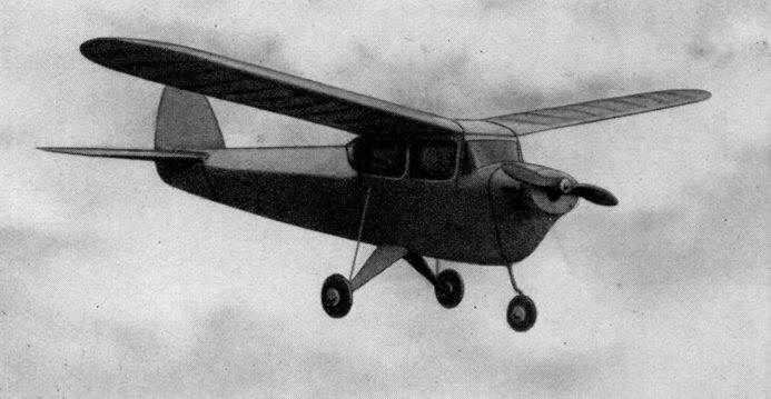
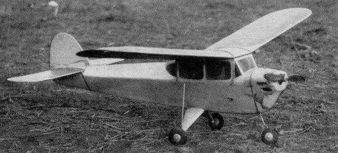
A Class A Gas Model That By SAL TAIBI
HERE it is at last, fellows; a model airplane that flies and glides like a contest model and yet looks like a Real Plane. It is an airplane that one will be proud to take to any contest - - - it has "fly-ability plus." You may have owned models that had a good climb but we believe nothing can compare with the "Meteor." The original ship was flown with a Bantam engine, would zoom around the sky at about sixty miles an hour and when the motor cut out it was just a speck in the sky. The glide couldn't be beat, it seemed like it would never come down. The Meteor is a model that really wanted to defy the laws of gravity. If you haven't built your contest model for this summer's flying and are trying to find something suitable, stop looking and get started on one of the finest designs we've ever flown! The "Meteor," a model designed by one of this country's leading aeronautical experts, Charles H. Grant. Building and Flying the "Meteor" Fuselage Before attempting to build the Meteor the plans must be scaled to full size. It is only necessary to scale up the crutch on the fuselage as all other parts are given full size. After the crutch is constructed, cut bulkheads 3,4, 5, 6, 7, 8, 9, out of 1/8" sheet balsa and bulkheads 1, 2 and 4A from 1/16" plywood. Place them in their respective positions on the crutch and cement thoroughly. Allow to dry a while, then add top rear longeron which extends from bulkheads 6 to 8 ; the top cabin longerons are then added. Both the top longerons and crutch are constructed from 3/16" sq. The keel is then cut from 1/8" sheet balsa; two are needed as the keel is laminated, a balsa gusset cut from 1/4" sheet is glued to the firewall and keel. The rear landing gear and shock absorbers are bent to shape and glued in place with 5/16" sq. grooved basswood, (See landing gear detail on plate I.) The fuselage is then covered with 1/16" sheet balsa; it is advisable to use three-inch widths for this purpose. The motor mount is then glued to the firewall, reinforced with 1/4" sheet gussets. A piece of 5/16" x 3/8" basswood is now glued beneath the gusset on B-2 and the crutch. (See nose detail on plate I.) Drill a 1/8" hole at the top of B-2, at the thrust line and another at the bottom of B-2 right above the keel between the 1/4" sheet gusset and the 3/16" sq. reinforcement. A 1/8" dowel is firmly cemented into each hole and allowed to protrude about 1/8" ; these serve to keep the removable nose unit from shifting; see nose detail on plate I. The removable nose unit is slipped into place and a 1/16" hole is drilled through section A and B ; a 1/16" dowel is then slipped in, serving to hold the removable nose unit in place. The front landing gear is bent to shape and cemented in place with 5/16" sq. grooved basswood. When the Meteor is assembled and ready to be flown, rubber is passed around the front landing gear and the wire hook on the bottom. A piece of plywood 1/16" x 1-1/8" x 6-1/4" serves as the ignition track, this is cemented in place below the 1/4" sheet filler at the motor mount rear; see motor unit detail on plate I. After this has dried the coil, condenser and batteries are wired as shown in the wiring diagram; you will note the ignition is mounted on bottom of the ignition track. If in doubt consult the plan side view. On the wiring detail you will notice the timer is fastened permanently into the fuselage; fasten it to a piece of 1/4" sheet, then glue the sheet balsa to the fuselage bottom. Now glue the Fahnstock clips to the fuselage near the crutch, a wire is soldered from each timer point to the clips. When the ignition track is wired up the two wires that go to the timer are left free ; when the motor unit is installed into the fuselage these wires are inserted into the Fahnstock clips. The nose block is formed from a piece of balsa 2-3/4" x 5" x 6". The block is glued lightly to the fuselage and the outside shape is cut and sanded. The block is then removed from the fuselage and the cowling center is cut out as shown on the cowling detail on plate 2. The front of the cowling is recessed about 1/16" ; 1/16" tubing is inserted in this space to give a radiator effect. The cowl is cut in half and the 1/16" pegs are inserted in place to properly hold the halves together. The windows are covered with celluloid and the fuselage is now ready for covering. Wing The wing is first scaled to full size, it will be noted the wing has no taper and the tips are perfect half circles that are drawn with a compass. The ribs are spaced 2" apart. The center ribs are made of 3/32" sheet to take the strain of the rubber when the wing is fastened to the fuselage. It will be necessary to elevate the front wing spar about 1/16" from the board because of the airfoil undercamber. The ribs are then slipped onto the spar in their respective positions, then the leading and trailing edges are cemented in place. The tips, which are formed on the plans before the wing is built, are cemented in place. The top spar is cemented in place. After the wing is removed from the board the rear spar is glued in place. Repeat this procedure for the other wing half. The wings are then sanded and joined at the correct dihedral angles, which is 3-3/4" at each tip. The final step is the sheet covering and cap stripping. The top is covered with 1/20" x 2" and the bottom with 1/20" x 3"; the cap strips are 1/20" x 3/16". Stabilizer The stabilizer is shaped same as the wing, in that it has no taper, round tips and also drawn with a compass. The stabilizer outlines are first constructed on the board. The leading edge is pinned to the board and the other parts of the outline, tips and trailing edge are raised off the board 1/16". With a pencil mark the edges where each rib fits on the leading and trailing edges, then remove the outline from the board. The ribs are now glued in position at the pencil marks. The top and bottom spars, 1/8" x 1/4" are cemented in place. The stabilizer top and bottom is covered with 1/20" sheet balsa at the center. Rudder The rudder is built flat; the plan is self-explanatory. After the rudder is built it is glued to the stabilizer top and a fillet is formed with 1/16" sheet balsa. Covering The original Meteor was tissue covered; the body with blue tissue and then painted all blue, the wings and tails double covered with orange tissue cross-grained and then trimmed with blue paint. Give the model at least five coats of clear dope before painting. Flying Before flying the ship be sure there are no warps in the wings or tails. We have thoroughly test flown the Meteor and all adjustments are on the plans, but as no two models are built alike in respect to balancing, your plane should first be glided until a long flat glide is obtained. On the first flight it should be flown at half power with an engine run of about ten seconds. If the Meteor performs satisfactorily fly it again with a 20 second motor run, gradually increasing the power on each successive flight. Good Luck ! If you have any questions about the Meteor, write to Sal Taibi, in care of MODEL AIRPLANE NEWS, 551 Fifth Ave., New York City. Scanned From September 1941
|