|
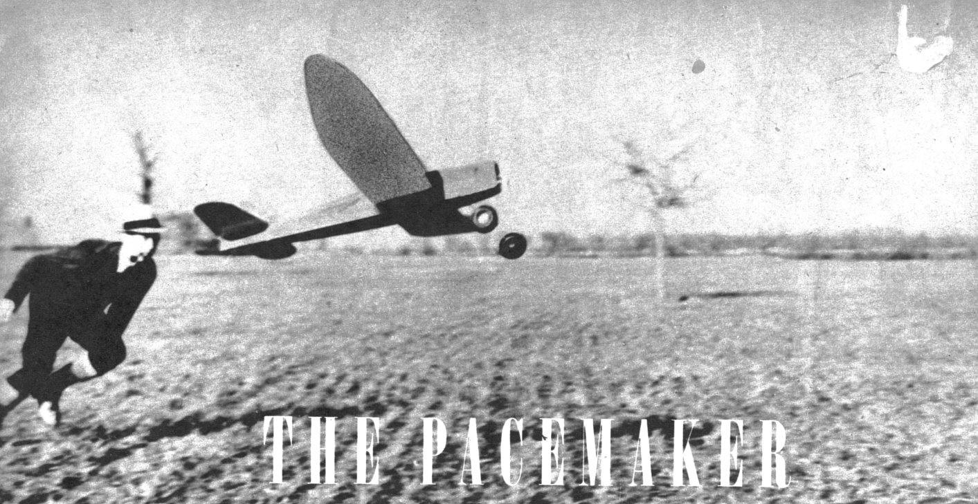
Taking off into a high wind, the Pacemaker proves its
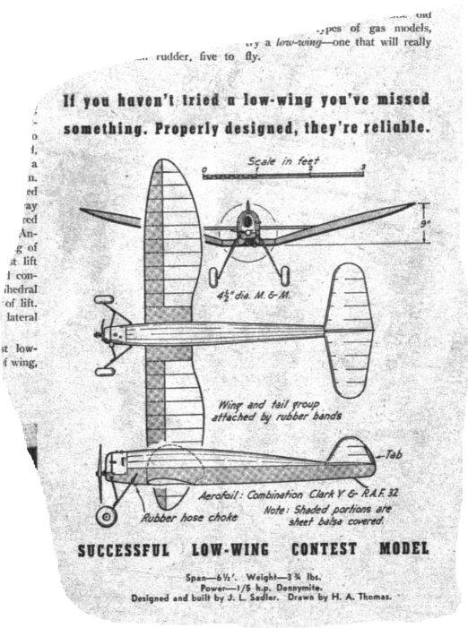
all-weather stability. THE PACEMAKER DESIGN BY J. L. SADLER
THE low-wing model which is the subject of this article has a background of several other similar models with which numerous experiments were tried in order to fully test the elements of design which the model incorporates. In other words, prospective builders who may feel a bit skeptical toward some features of the model can be assured that it is sound in performance and construction. A previous article in this magazine briefly mentioned some of this model's "radical" features. such as: extremely low line of thrust, dihedral of 1-1/2" per foot of span, long propeller moment arm (which means a long nose), small rudder, and others. Numerous flights under practically all flying conditions have failed to show a single structural weakness or peculiarity of performance. Incidentally, after nearly a hundred flights the model is flying at the time of this writing with the same propeller with which it was first tested. The model is powered by a Dennymite, although any engine of approximately the same power may be used, the Brown and Ohlsson Gold Seal being two examples. CONSTRUCTION There are probably many inexperienced builders who will hesitate before building this model because they are faced with the necessity of enlarging the plans to full size. There is no reason why enlarging the plans should be a long or tiresome task. All that will be needed are the wing, stabilizer, and rudder outlines and the lower part of the fuselage frame. All wing ribs and fuselage bulkheads are included at full size. Begin with the wing plan by laying out a grid of 1/2" squares in pencil on any kind of paper -- brown wrapping paper will do. Then by checking with the smaller grids on the printed plans, mark each place a part of the wing outline intersects a grid line. This is done by eye. Then lightly draw in the outlines, passing through all the points previously marked. Check again with the printed plans and make sure the enlargement looks proportional. Now the curves may be drawn in more heavily. Bend a strip of 1/8" square balsa to draw along for the more gentle curves. For the abrupt curves use a celluloid curve or draw in the lines free-hand. Plot up only one half of the wing and the center section. Make two sets of wing tips and trailing edges from the same drawing. Then it will only be necessary to make a rough sketch of the spar location and the rib spacing on which to assemble the opposite wing panel. Before starting construction, make a careful study of the plans and get a clear understanding of the construction of all parts of the model. At this point, we want to make a plea to those builders who are inclined to rush things. Spend whatever time is necessary to do a neat and accurate job and do not let the anticipation of flying the model cause you to be satisfied with a second-rate covering job or a plane that "almost lines up." This particular model is intended to be flown with no warp, washin, or washout in either the wing or tail. These surfaces should be absolutely true. The desired flight turns are taken care of by rudder tab and thrust-line adjustments. Fuselage. Cut all plywood parts, bulkheads, motor mount pieces, et cetera, before starting with the assembly of the fuselage. Notice the top longerons are in a straight line when viewed from the side. The flat supports shown on the plans are 3/4 x 1/8" strips of white pine. Make both sides of the bottom part of the fuselage. Turn them upside down and with the top longerons flush with your work bench, put in the cross pieces. After this is dry, turn this work over and cement on the bulkheads and stringers. The lack of diagonal braces may make it a trifle difficult to keep the fuselage in alignment, but when the fuselage is covered it becomes rigid and the diagonals are not needed. Use hard materials throughout the fuselage. Fit all joints carefully and cement them liberally. Notice that the lower longerons are reinforced with 1/32 x 1/2" balsa strips. This is to prevent sagging of the longerons between the cross braces. These are not needed on the upper longerons. Cement thoroughly the motor mount pieces to the pine strips and plywood and nail with small brads. Make sure the motor mount is parallel to the top longerons and flush with the pine support. This gives the motor zero downthrust. Mount the tail skid, which is made of 3/32" diameter steel wire. Install wing hooks as shown on the plans. Do not mount coil and battery until the model is completely finished, as their location is used to properly balance the model. Cover the bottom of the fuselage from the wing trailing edge rearward with glider cloth or light airplane fabric. The rest of the fuselage is more easily covered with silk than with paper. Spray with water and give three or four coats of heavy airplane dope. Mount the engine as shown, using wood screws. Wiring. Install whatever type of booster battery connections you prefer. Mount the flight timer on the same side of the fuselage that the boosters connect to, and install all wiring except to the coil (which will be mounted later). Make all soldered connections secure and use the minimum lengths of wire needed. If it is necessary to extend the high-tension wire from the coil, be sure to insulate it thoroughly. A broken wire can cause no end of trouble, so guard against this by using large wire of good quality. Landing Gear. The landing gear used is very simple and flexible. Drill through the plywood and pine support as indicated and insert the wire pieces separately. Solder large washers as shown, bind and solder the struts where they converge, and attach the airwheels. Cowl. From a medium-weight block of balsa, saw the front part of the cowl to general shape. Carve to finished shape, sand until smooth and, with the engine in place, fit it into place. Notch out inside wherever necessary to clear spark plug, motor lugs and timer. Cement small wire spurs into the motor mount, which fit into holes in the bottom of the cowl front. Cement another small wire spur at the top of the cowl which fits hole in the aluminum hood. This secures the cowl. Dope the front part several times, sanding lightly between coats, and shellac the interior. Set the front part of the cowl in place and, using a piece of writing paper, make a pattern of the aluminum hood. Let the hood overlap 1/8" at the front and back, and 1/2" at the bottom on each side. Make an extension to the gas tank and let it slightly protrude above the cowl. Solder an extension to the needle valve and let it protrude slightly above the cowl when screwed down. Solder a large washer to this extension and use a small piece of sponge rubber between the cowl and the washer to absorb vibration. The average aluminum pie pan is of the right thickness for the hood. Cut the rear air vents as shown. The hood is held in place by four small, round-head wood screws. Make, sure the high-tension lead or spark plug cannot short circuit through the aluminum hood to the exhaust pipe. The lower part of the cowl, below the fuselage, is simply a piece of aluminum which is nailed to the fuselage with small brads. Aluminum is used here since it does not absorb oil and permits it to drip out at the rear. Wing. Begin by cutting eight "A" ribs, four "E" ribs, and two each of the others, using medium 1/16" sheet balsa. Select hard 3/16" square strips for spars and leading edge. The trailing edge is V-shaped and is formed of hard 1/32" sheet. The parts forming the trailing edge are so laid out that they may be cut from two-inch-wide sheets of balsa. The solid splice shown on the plan of the trailing edge refers to the lower part, while the dotted line indicates the splice for the upper part. By working directly over the enlarged wing plans, assemble the outer parts of the wing and the center section. The bottom surfaces of the outer panels are flat, so the lower parts of the spar and trailing edge may be pinned to the plan. Cement ribs in place, pin and cement the upper spars into the notches, and cement the upper half of the trailing edge. Fill in 1/32" pieces of sheet balsa between all ribs, cementing them to the spars with the grain running vertically. Reinforce wing spars at the dihedral angles as shown. Place the leading edges into the notches and cement thoroughly. The sheet-balsa covering for the leading edge may have to be applied in segments, due to the slight upper curve in the wing. The entire center section is covered above and below with 1/32' sheet. In covering wings and tail groups, many builders make the mistake of not cementing the covering to the ribs. This provides greater strength and, in case of tears, it prevents the entire covering from loosening. Tail Group. The tail is quite simple and the builder should experience no trouble with it. Take care that it is not warped. The leading edge of the stabilizer is cut from one continuous piece of 1/8" sheet balsa. The trailing edge is similar. Notice that the stabilizer has 1/4" of positive incidence at the leading edge. This is formed by cementing tapered balsa strips to the upper longerons. If test flights indicate this to be too much incidence, it may be reduced by sanding the strips. Install the tail attachment fittings as shown, making sure that they fit snugly against the longerons. The wing and tail are both covered with heavy bamboo paper, sprayed with water, and given three coats of heavy dope. Assembly. Before balancing the model, check all parts carefully and remove any warp by steaming. The model can now be painted as the builder desires. Red and' ivory lacquer were sprayed on the original. See that the model is now completely assembled with propeller, cowl, and all other parts except the coil and battery. Balance by fingertips at the widest part of the wing, one third back from-the leading edge. This trial balance will give you some idea where the coil and battery must be placed. Now mount the coil permanently and balance again. Mount the battery with rubber bands and make provision for moving it slightly if it becomes necessary later. Stick a pin in the top of the fuselage at the front of the rudder, turn the propeller horizontally, and with a long rule measure the distance from the pin to each propeller tip. For the first flight this thrust adjustment should be zero -- that is, the dimensions should be the same. After the test flights it may be necessary to slightly adjust the engine to right or left. Bend the rudder tab very slightly for a large right turn. The engine torque should spiral the model rather steeply to the left, and in the glide the tab should make the model turn to the right. Flying. Make the first test glides by running swiftly, guiding model on the ground by a wing tip. After making sure it will not dive or stall radically, glide it from shoulder height into the wind with the nose slightly depressed. Make whatever adjustments may seem necessary and fly the model at first with the engine running at half speed. When properly adjusted the model flies very fast under power, and quite slow in the glide. Always remember that wings and tails can warp after a period of time. A careful check-up of the airplane should always precede the day's flying. This model asks no favors because it's a low-wing. Give it half a chance and it will prove as reliable and rugged as any other type. SPECIFICATIONS
Scanned From January 1940
|