|
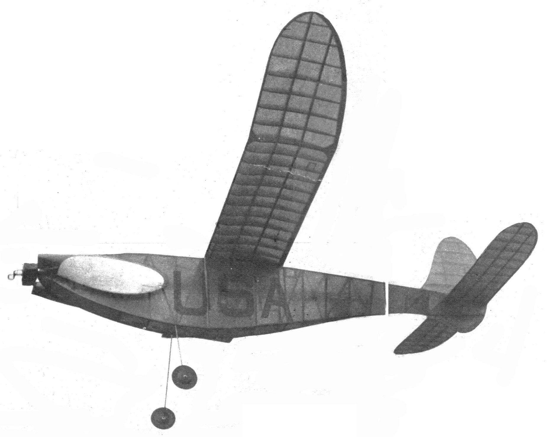
1940 MOFFETT ELIMINATIONS WINNER The Nationals were its first competition.
HERE are plans for a ship that is just a bit different from the conventional design of fuselage models. It features an eighteen-inch two-bladed folding prop which gives it a motor run of about 1:15. The ship was flown in competition for the first time in Chicago. Here it proved to be a winner by making two out-of-sight flights, the original model being lost on the last flight. Longest flight was 6:35. Total time for three flights being 834.1 seconds. CONSTRUCTION Begin by making full-size layout of fuselage for which full-size dimensions are given. Cover this with wax paper. Longerons are then pinned on the working drawing and all uprights and diagonals are cemented in place. Note that pins are not put through the wood but along the edges. Both sides are made at once, one on top of the other. Let cement set overnight. Sand outer edges of sides while stuck together. This will produce two sides identically the same. Separate sides with thin razor blade. In joining the two sides, start at the widest point and gradually work toward the ends. Use chart for obtaining dimensions of cross pieces. Dimensions in chart are given for overall width. Subtract a quarter-inch from these given dimensions for actual lengths of cross pieces. Use small rubber bands to help hold sides together while cementing cross pieces in place. Check alignment of fuselage as work progresses by placing fuselage, top side down, on a flat surface and with a square held perpendicular to the thrust line against top longeron measure distance between square and bottom longeron. This distance should be one-half the difference of the top and bottom widths of that station. All cross pieces are 1/8" square except the pieces of Stations 7, 8, 9, 10, which form the wing seat. These are made of 1/8" sheet. Fill in between Stations 1 and 2, 15 and 17, with 1/8" sheet all around except top section between Stations 16 and 17 which is covered with celluloid. Rear hook (3/16" dowel) bearing plates are made of 1/16" sheet aluminum. Drill 11/64" hole-in center of plates. Flange corners down with pliers and force in place and cement. Ream holes with small round file until 3/16" dowel fits snug. Landing gear is formed from 1/16" music wire to pattern on Plate 1. It is glued and bound to uprights in Station 6. The uprights are braced with 1/8" sheet gussets fore and aft. Cover with red Jap tissue. Spray with water before doping. As for the wing, make a full-size layout of this. Cut out wing rib template from .015 sheet aluminum. With aid of template cut out ribs from 1/16" medium sheet balsa. Wing tips are made from 1/8" medium sheet balsa. Assemble wing in conventional manner. When cement is thoroughly dry, break wing in three places for polyhedral. With the aid of blocks and pins to hold wing in proper position, cement breaks, reinforce with 1/8" sheet gussets. Let cement set overnight. Sand wing tips, leading and trailing edges and cover with red Jap tissue. Spray with water and give two coats of dope. The stabilizer construction is similar to that of the wing. The rudder frame is cut out of 1/8" medium sheet balsa. Ribs are pieces of 1/16 x 3/16" medium balsa sanded to shape after assembly. The subrudder is cut out of 1/8" hard sheet balsa. Cover rudder and stabilizer with red Jap tissue. Rudder is temporarily tacked in place. The rudder is offset a little to the left to counteract torque and to give the ship circle to the right in the glide. After model is adjusted for proper circle the rudder is then permanently cemented in place. The prop is carved out of medium balsa. Blank is cut to dimensions given on Plate 1. After prop is carved it is cut in two at the exact center on an angle of about 15 degrees. The hard balsa center block is then made. Drill 5/64" hole in exact center of block for prop shaft. The ends of this block are cut to fit the blades. Metal fittings are made according to details on Plate 1. Nose block is made of hard balsa. A hardwood dowel is inserted in proper position. Wood screw stop is mounted in this dowel. Folding mechanism is simple. When rubber is wound, its tension draws the prop shaft backward, bringing the shaft arm beyond the screw stop. As prop revolves and rubber tension decreases, the wire spring draws prop shaft back to original position where the shaft arm catches on the screw stop, at which point the blades fold back. Rubber motor consists of eight strands of 1/4" flat 80" long. Using a four to one winder, put in forty winds and bring ends together. This takes up excess slack and acts as a rubber tensioner. Small rubber bands are slipped on each end to prevent rubber from crawling off bobbin. Use a good grade of brown rubber and keep it well lubricated. FLYING Test model in calm evening air. Offset thrust line one degree to the right and about two inches down. Wing incidence is one-quarter inch. Glide by hand to find proper wing position. Now give rubber about seventy-five winds with a winder and launch into the wind. Model should climb against torque and glide in cir- (balance of article was missing g.t.h.) Scanned from July 1941 |
