|
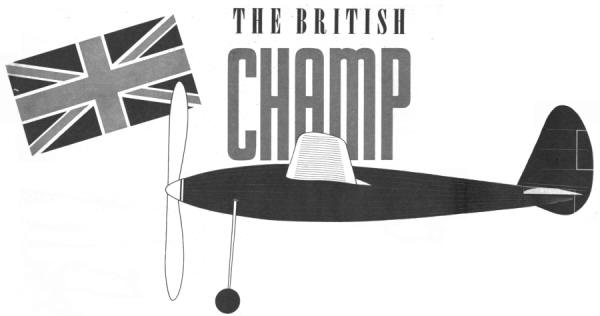
An ultra streamliner that set an international mark of
33:09 to win
the King Peter Cup.
BY ROBERT COPLAND
DRAWINGS BY PAUL PLECAN
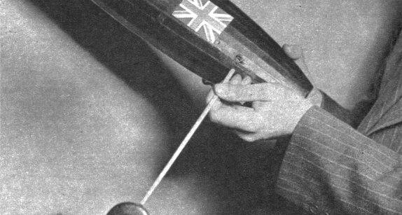
A one-quarter-scale side view. |
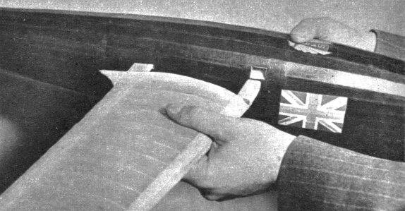
Butt ends of wing spars fit into sheet balsa boxes in the fuselage. |
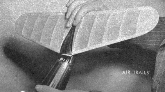
Stabilizer fits info last bulkhead; held down by detachable rudder. |
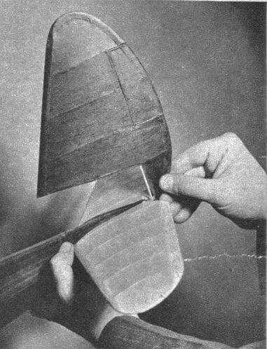
Detachable rudder fits into tubular stern post. |
|
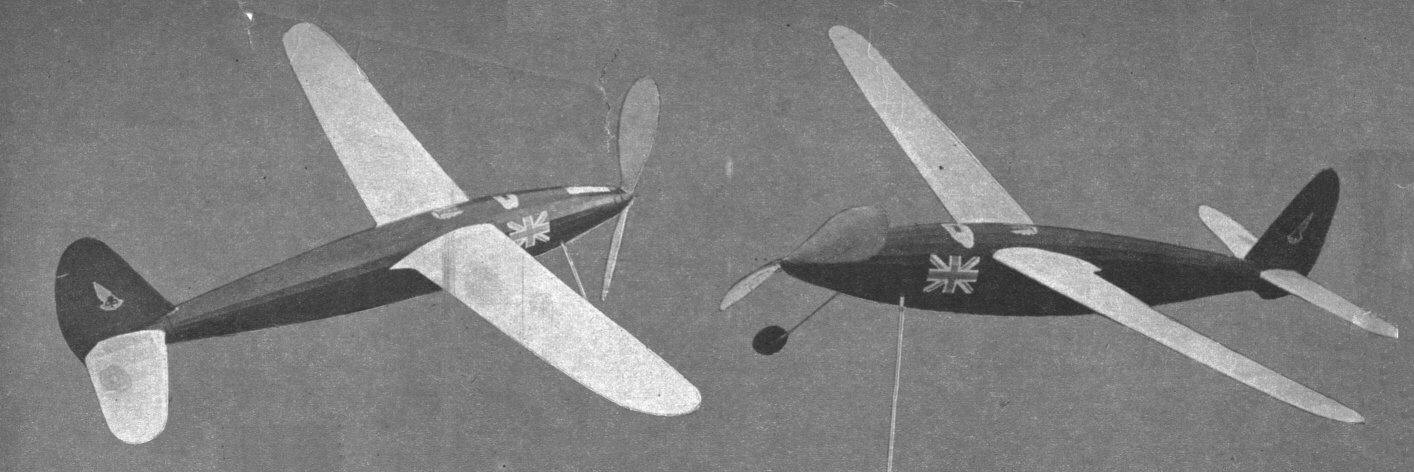
From spinner to tail fuselage is one unbroken
streamline. Wings are carefully faired into fuselage. |
|
Robert Copland has been hot on the trail of the
Wakefield Trophy for the past five years. He's come close but has
never finished in No. 1 position. In view of his record in other
contests it seems remarkable, that he hasn't won it. He placed third
at the 1936 Wakefield in Detroit. While in America that year he flew
in our national contest and placed a good second in the Stout Outdoor
Fuselage with 20:07. Back home in England that same year he won the
1936 British Cup Competition. The Pilcher and the Weston Cups were
gathered into the Copland collection during the 1937 English campaign.
In 1938 he set an international record for rubber-powered cabin
fuselage with 33:09 at the King Peter Cup Competition in Yugoslavia.
(This record stood until Korda's 1939 Wakefield flight.) Last summer
he was fourth in the 1939 Wakefield finals at Bendix, New Jersey.
His outstanding work has been done with
rubber-powered fuselage jobs. But he's also one of England's best
indoor builders. His flights of over 18 minutes for hand-launched
stick models are listed on the official English records.
Americans have come to regard Copland as a
permanent member of the English Wakefield team. He was a member in
1936 and 1939 -- the two times the English have visited us for the
finals. He takes his contest flying seriously and works about the
hardest of any contestant we've seen. When his model got off on a long
flight at the last Wakefield contest, he didn't wait for help but dug
in and did the roadwork himself in mighty fast fashion -- which is the
acid test of one's model enthusiasm. Watching him in action gives the
impression that sooner or later the Wakefield Trophy will some day
bear his name.
The British Champ is the design that set the 33:09
international record mentioned previously, and that took fourth in the
1939 Wakefield. This ship was favored to win the Wakefield and had
averaged well over, four minutes on all of its test flights, made the
night before. That it did not place higher was due principally to the
extreme heat conditions with which foreign contenders had no previous
experience.
Having seen this job perform at Bendix, we wonder
just what it would do with an American high-powered rubber motor. (Due
to scarcity of thermals at English contests, the boys over there find
low-powered, long-running motors to be best.) -- Gordon S. Light. |
CONSTRUCTION
THE wing has to be constructed first, as it is used to
place the wing mount channels in position. All the wing ribs are given
full size, and both sets should be cemented to a sheet of stiff bristol
board. After two of the # 1 ribs have been cut from 1/16" sheet, the
template should be trimmed down with scissors or a razor to the next
smaller size. Two ribs of each size (#2 to #21) are needed, and all should
be cut from 1/20" medium balsa sheet. The wing tip is given full size, and
should be cut from medium-hard 1/8" sheet. The leading and trailing edges
should both be tapered to the sizes indicated on the plans, and it is a
good idea to trim the trailing edge to the approximate finished cross
section, as it is harder to trim it once it has been cemented in place. In
assembling the wing panels, the leading edge should be raised off the work
bench by inserting scrap bits of 1/32" sheet balsa at regular intervals
along the length of the leading edge.
The trailing edge should be propped up with 1/16" scrap
balsa placed under the front portion to keep it at an angle to the work
bench while the ribs are being cemented in place. After all the ribs have
been cemented in place, the wing panels should be left aside to let the
cement dry completely, as the wings might warp if they are removed from
the workbench before the cement has had a chance to dry. The trimming of
the butt ends of the leading and trailing edges is shown on the plans, and
should be done with accuracy and care. Both the leading and trailing edges
are trimmed on the bottom to obtain 4" dihedral when the wing rests flat
on the bench on the portions that have been trimmed. Two channels, 4"
long, are now made of hard 1/16" sheet. The inside dimensions of the
leading edge channel are 9/16 x 5/8"; trailing edge channel, 3/l6 x 7/8".
Both channels should be wrapped with silk or bamboo paper, with an extra
coat of cement applied over it. When trimming the butt ends of the wing,
make sure that the wings fit snugly into the channels.
Fuselage. Draw a center line on a strip of paper
36" long, or directly on the workbench. Mark off the correct spacing
between the bulkheads, and draw in the widths, which can be taken directly
from the full-size bulkhead outlines. Cut the correct amount of each
bulkhead (four in most cases) and cement two of each size together. Use
hard 1/16" balsa for the bulkheads as they are narrow and would be
slightly on the weak side if light balsa were used. Cut out only two #9
bulkheads of the narrow type, as the upper portion of #9 is different from
the rest of the bulkheads. Each bulkhead is made up of upper and lower
portions, each portion 1/8" thick, due to the fact that it is laminated
from two 1/16" thick bulkheads. Since only the bottom half of the fuselage
is built first, do not cement the entire bulkheads together. Pin all of
the bulkheads in place, propping each one up with scrap 1/20" sheet. The
proper steps in constructing the fuselage are shown under the side view of
the fuselage. The top and side longerons are the first ones to be cemented
in place, followed by a longeron between each side and top longeron.
Remember that all longerons are cemented over all bulkheads except #1 and
#16. On #1 and #16, the longerons are butt-cemented against the bulkheads,
the outside edge of each longeron being flush with the outside edge of the
bulkheads.
In Step 2, the remaining longerons are cemented in
place, two between the longerons already in place. Complete the tail end
of the fuselage behind #16, and let the cement dry thoroughly before
removing the lower half of the fuselage from the workbench. After removing
the lower half from the bench, turn it upright and proceed to add the
upper halves of each bulkhead. A typical bulkhead should now appear the
same as Step 3. The longerons on the upper half of the fuselage are spaced
the same way as those on the bottom, so repeat the procedure used in
spacing the lower longerons. The nose and tail ends should now be filled
in with scrap 3/32" balsa to provide surfaces to be gripped when the motor
is being wound. The rear wing channel should be cemented in place in the
space allowed in the cut-outs on pieces "T" that are cemented to the rear
of bulkhead #9.
After the cement has dried, slide one of the wing
panels on. Insert the front channel over the wing leading edge, and then
insert the other wing panel into place in both channels. The bottom of the
front channel should be 1-3/16" above the fuselage center line, and if it
is, fill-in pieces should be cemented around it on both sides of the
fuselage. If the front channel is too high, remove both wing panels, and
correct the position of the "T" pieces by cutting them away and
recementing them in place again, at an angle more parallel to the thrust
line. Fill in the areas around the channels, trim the channels off near
the fuselage, and sandpaper them flush with the fill-in portion. The
landing gear struts are made of bamboo, and are of streamlined cross
section, to keep them from revolving in the paper tubes into which they
slide. Four layers of brown wrapping paper makeup the tubes. They are made
right on each strut, cement being applied between each layer of paper for
stiffness and strength.
The tubes are cemented to bulkhead #4 at the top, and
are separated from the bulkhead with 3/16" thick blocks at their lower
ends. As shown in the sketches, triangular gussets are cemented to the
tubes at the upper and lower ends to take up landing shocks. A small area
around the tubes should be filled in to provide extra strength. In the
sketch of the tail end of the fuselage under the side view, note that
there are hard balsa slabs cemented to the inside of the fuselage where
the 3/16" dowel passes through, as this portion must be rigid to take up
twisting strains and the forward pull of the motor.
We used a rod of some plastic material like celluloid
to anchor the rear end of the motor, but a wooden dowel will do, besides
being more readily available. The 1/8 x 1/4" strips on the rear of the
fuselage should be cemented in place now, followed by piece R-10, the top
of which, should be flush with the top of the 1/8 x 1/4" strips. Cement
R-9 in place now, and cut out a # 1 bulkhead from1/32" plywood, which is
also cemented
in position. The fuselage is now covered with small
squares of tissue, with the grain in the tissue running around the
fuselage instead of parallel to the longerons, as commonly applied. Use
small squares of tissue, about 4 x 4" on the front of the fuselage, as the
curves are too sharp to allow covering with larger sheets. Larger sheets
can be used near the tail (#12 to #16) as that portion of the fuselage is
nearly flat, and almost half of the fuselage side can be covered with one
piece. If your technique "isn't so hot," use small sheets throughout, as
much neater results can be obtained that way.
Landing Gear. A full-size wheel detail is given
for those who wish to duplicate the original "hubless" wheels. Procedure
is simple. The disks #1 and #2 are cemented together first, followed by
the insertion of the short tube, which is cemented and recemented to #1
and #2 until there isn't any more room left for more cement. The wire axle
is inserted now, and a small metal piece "X" is soldered on. Disk #3 is
hollowed out slightly in the center to allow space for the axle and piece
"X." The wheel is now sanded to shape and doped with several coats of
clear dope. The axle is now cemented to the bamboo strut, bound with
thread, and cemented over again with another coat. The bamboo struts
should slide into place snugly enough to make sure that they do not drop
out in flight, as that is not allowed in contests, whether it is
intentional or not. A few coats of dope will make the struts a snug fit if
they are loose.
Stabilizer. The stabilizer is of ordinary
construction, except for the fact that, like the wing, heavy leading and
trailing edges replace spars. The small former "S" fits under bulkhead #16
when the stabilizer is in place, and "S-2" is of the same shape and height
as #16. Small stringers are used to fair in the top of the stabilizer with
the fuselage, but they should be added only after the stabilizer has been
covered. While we are on the subject of covering, a few hints on the wing
covering should be timely. The wing has an intentional warp in both
panels, and by covering the wing with the grain of the tissue running
chordwise, the warp as used in the original model can be duplicated. When
the tissue has been applied and sprayed, the panels are laid down flat on
the bench and weighted down with small objects, such as an ink bottle,
pliers, or anything that does not weigh more than about eight ounces. The
entire leading edge should be resting on the bench, but the wing-tip
portion of the trailing edge should be propped up 1/8" near ribs 18 or 19.
The center section of the trailing edge should be touching the bench the
same as the leading edge.
After the tissue is dry, the wing should be removed and
doped on the undersurfaced part, this being done with a 3/8" wide brush
for speed. The wing should be weighed down the same as before, and the
upper surface doped. After a long period of drying, the wing should be
removed to check up on the warp. Whether it is warped or not, the above
doping procedure should be followed with two more coats. After the last
coat, the panels should be left in the weighed-down position overnight to
make sure that the warp doesn't fade away after the wing has been removed
from the bench. If you are not successful in obtaining a warp in the
wings, do not worry about it, as the model flies slowly under power. You
need not worry about a stall under the initial burst of power, as a little
right thrust will correct that. The purpose of the warp is to decrease the
drag of the wing tips while gliding, as the wing is always at an angle to
the airflow.
Rudder. All curved parts and ribs are given full
size. Note how the hinges are made. The best material for hinges is
aluminum, as it bends easy and is light. It is important that the ends of
the hinges be twisted, as the trimming tab may slide off the hinges if
they are left straight. Ordinary cement does not hold onto aluminum very
well, as there are no large pores for the liquid to seep into and get a
grip on.
Propeller. The propeller is carved in the usual
manner, using the layout on the plans. The undercambered portion of the
prop blade need not be carved away excessively, as the original had but
3/32" undercamber. After covering with silk and doping, two small blocks
on each side of the prop should be carved into a spinner, the rear of
which is hollow to contain the free-wheeling unit. A full-size cross
section detail is given, so all shaft and freewheeler parts can be bent to
shape directly over the drawing. The front of the shaft is bent to shape
first, starting with the winding loop. A small brass washer is soldered on
the shaft behind the loop. Before sliding the prop into place, a tube
should be inserted through it or bushings used to insure smooth rotation
when the prop is freewheeling. The wire piece "U" is soldered in place
next, after the prop has been slipped into place. After piece "L" is in
place, twist the shaft clockwise (looking from the rear) to see if you can
make "L" and "U" lock, as it should be under power.
Bend the front end of "L" over now to keep it from
slipping off while you worry about the rest of the model. A ball-bearing
washer is used behind "U," behind which the nose plug belongs. The nose
plug is made from very hard balsa cemented together and also clamped with
a threaded bushing. A bobbin slipped in place before completing the hook
at the rear end of the shaft completes the prop assembly. For those who
have been wondering why, the bobbin is used to keep the motor from
bunching up on the shaft, an evil quite prevalent when the plain type of
hook was used. Since the wing cannot be shifted forward or backward in
adjusting, a weight which can be moved at will is attached to shift the
center of gravity a wee bit for perfect adjustments. A sketch accompanying
this article should help to clear up the idea. The climb should be long
and gradual and the glide flat. On the original model, the fourteen
strands of 1/4 x 1/30" rubber kept the prop spinning for 1-1/2 minutes,
after which the model glided for 2-1/2 minutes, producing an average
flight of approximately 4 minutes' duration. The maximum number of turns
is 1,200, under ideal conditions.
BILL OF MATERIALS
(Balsa, unless otherwise specified)
| 2 pcs. |
1/16 x 3 x 36" hard balsa |
bulkheads, wing channels |
| 1 pc. |
1/32 x 2 x 2" plywood |
former #1.
(1/20" plywood will do.) |
| 24 pcs. |
3/32" sq. x 36" medium balsa |
longerons |
| 2 pcs. |
3/32 x 1/2 x 36" soft balsa |
fill-in material |
| 1 pc. |
3/32 x 7/16 x 18", |
stabilizer trailing edge |
| 2 pcs. |
1/8 x 1/4 x 11-1/4" bamboo |
landing gear struts |
| 1 pc. |
1-3/4 x 2 x 18" medium-hard balsa |
prop block |
| 4-2/3 ft. |
1/4 X 1/30" brown rubber |
|
| 3 pcs. |
1/20 x 3 x 36", |
wing, stabilizer and rudder ribs |
| 1 pc. |
1/4 x 5/16 x 18" |
stabilizer leading edge |
| 1 pc. |
1/16" sq. or round bamboo, 18" long |
stabilizer tips |
| 1 pc. |
1/4 x 3/8 x 7" |
rubber leading edge |
| 1 pc. |
1/4 x 5/8 x 6" |
rudder base rib |
| 2 pcs. |
1/32 x 3/16 x 1-1/2" aluminum or brass |
rudder binges |
| 1 pc. |
3/32" diam. bamboo or dowel |
rudder spar |
| 1 pc. |
1/8 x 2 x 6", medium-hard balsa |
wing tips |
| 2 pcs. |
3/16 x 7/8 x 22" |
wing trailing edges |
| 2 pcs. |
9/16 x 5/8 x 22" |
leading edges |
| 1 pc. |
3/16" diam. x 2" long dowel |
rear motor plug |
| 4 pcs. |
1/16 x 2 x 2" |
disks #1 and #3 on wheels |
| 2 pcs. |
1/8 x 2 x 2" |
disk # 2 on wheels |
| 1 length |
1/16" diam. spring steel wire |
prop shaft |
| 1 length |
.040" diam. spring steel wire |
"U" and "L" fittings, wheel axles |
| 1 |
bobbin |
|
| 1 |
ballbearing washer |
|
| 1 |
threaded bushing |
|
| 3 sheets |
colored tissue |
|
| 2 |
bushings for prop
(or 1/16" inside diameter tubing) |
|
| 2" length |
tubing |
to fit over axles and fitting "L" |
Scanned from April 1940
Air Trails


 |