|
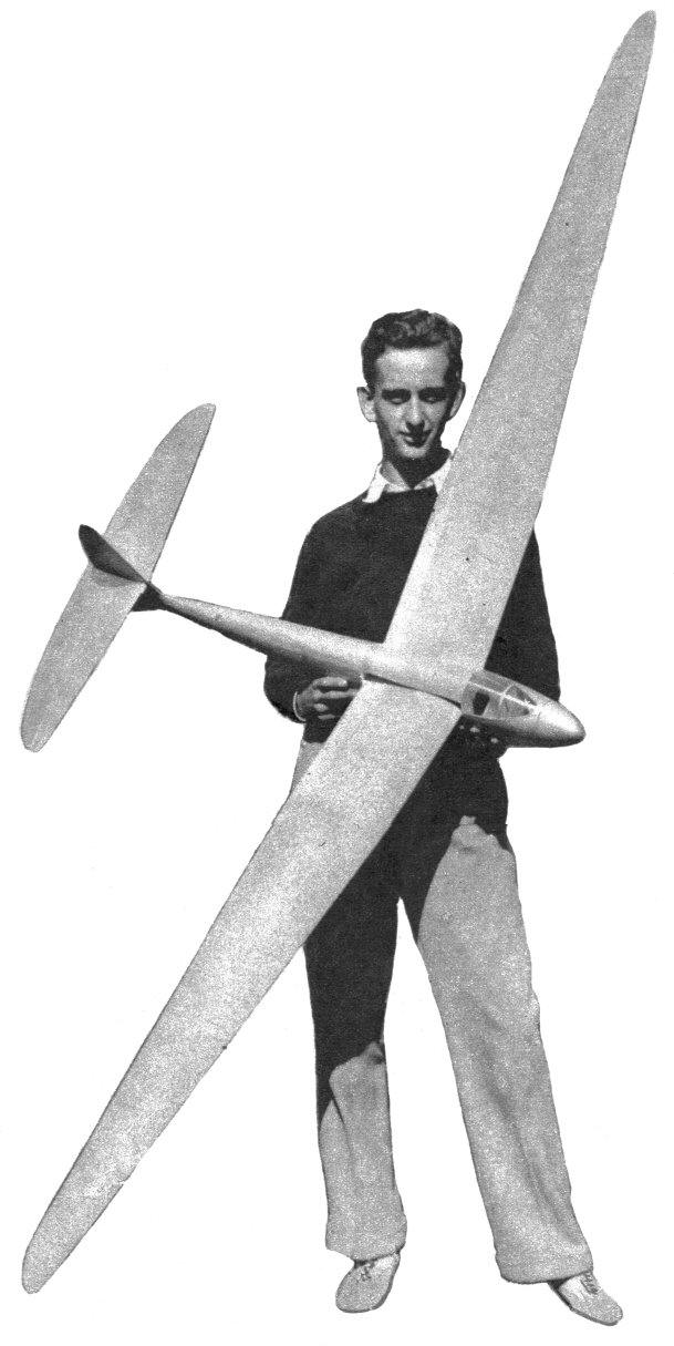
THE AIRHOPPER BY STANLEY ORZECK An eight-foot sailplane either towed by a gas model or launched by hand tow.
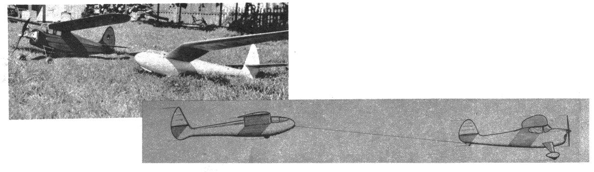
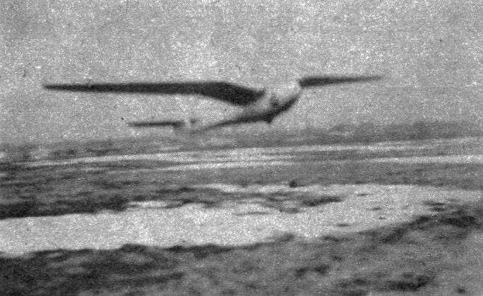
EIGHT feet of soaring grace, the gull-winged Airhopper provides a practically new kind of model flying. Its novel features, particularly a reliable automatic release -- workable for either hand or gas-model towing -- and its thermal -- sniffing ability are points of interest. The ship has really been flown successfully behind a gas job and, although a plane tow is tricky for beginners, detailed instructions and notes on performance will be found under the flying directions. The longest flight was just under an hour in duration, covering four miles. A cloudless sky kept the model in sight, and judging from the speck-like appearance in the air, the size of the ship indicated an altitude between 1,500 and 2,000 feet was reached. And this was from sixty feet of line. Imagine the consistent soaring flights possible with 500 feet of line ! A word to the wise. Don't shoot the works if those nice fluffy, cumulus clouds are around. The Airhopper will be in them in a jiffy. CONSTRUCTION Fuselage. Draw a centerline on a straight wooden plank and cut the bulkheads A to I from 1/16" sheet. The lower parts are cut away on the dotted line shown on the full-size bulkhead layout. Pin the bulkheads to the board at the proper spacing, line them up, then cement the 1/8 x 1/4" main longerons in their notches. Cement the 1/8 x 1/8" longerons in place as indicated in the side-view drawing. Add the "keel" longeron, along the bottom centerline of the fuselage. The landing-gear braces are shown in detail and are cemented solidly into the fuselage. Any 2" wheel will do, but an airwheel is best. A sponge wheel can be home-made by inserting a length of 1/16" inside-diameter tubing through a sponge ball, adding a 3/4" diameter disk to each side, and compressing the unit until it flattens into a wheel. The tubing will have to be headed over or peened to hold the disks compressed. The fuselage is covered with 1/16" sheet forward of Bulkhead E, and 1/32" sheet to the rear of E. The upper portions of the bulkheads are now added to the half-completed fuselage, and the two 1/8" square longerons installed. A 1/4 x 1/8" longeron is cemented along the top centerline of the fuselage. All the longerons should be flush with the outside of the bulkheads. An opening for the wing to slide through must be left in the fuselage sides. When covering the fuselage, the balsa should be cut into small rectangular panels so that it may be applied in much the same manner as used in all-metal transports. The cement dries too fast when large areas are covered. Tail. The lower portion of the rudder is built integrally with the fuselage, and the 1/32" sheet covering should fair into the fuselage and the rudder. Full-size outlines are given for nearly every part of the rudder. The diagonal braces inside the rudder are 1/8" square. Cover the rudder and cut the proper curve for mounting the stabilizer. The stabilizer spars should be perfectly straight. The stabilizer leading edge tapers from 1/4 x 3/8" to 1/8" square at each tip. After assembling. the leading edge and trailing edge of the stabilizer are covered with 1/32" sheet. The front of the leading edge of the stabilizer should coincide with the leading edge of the rudder when mounted. Assemble the upper portion of the rudder and, before covering, attach the tab with small brass or copper hinges. The tab is cut from 1/8" sheet and sanded to a triangular cross section. Wing. Full-size ribs are given. Cement the entire outline to a sheet of hard balsa, and cut six No. 1 ribs from 1/16" stock and six No. 1 ribs from 1/8" stock. Now trim the rib outline down to the next smaller size rib, and use it to cut two No. 2 ribs. After two ribs of each size have been cut out, the outline should be trimmed down to the next smaller size. The wing is built in three parts, the center section and two outer panels. Since the wing is of such high-aspect ratio, it will have to be built on an absolutely flat surface to avoid warping. When building the center section, slant the end ribs so that the proper dihedral may be had upon cementing all three panels together. The 1/8 x 1/4" upper and lower spars are joined together by cementing a small rectangular piece of 1/16" balsa between the ribs through the span of the wing, so that the spar thus formed resembles an "I" beam. See detail on plan. Note that the 3-5/8" dihedral in the center section is measured from the center to the tips, and not from the intersection of the fuselage and wing. The leading edge is covered with 1/32" sheet up to the spar line. Before covering the trailing-edge portion, cement in the 1/8 x 1/8" diagonals. The 1/32" sheet covering on the trailing edge is 1-5/8" wide. In making the outer panels, it will be necessary to taper the spars from 1/8 x 1/4" at the No. 1 rib to 1/8 x 1/8" at the No. 12 rib. The leading-edge covering should extend back to the spar and the trailing -edge covering should taper from a 1-5/8" width at the No. I rib to a width of 1-1/4" at the tip rib. When all these panels are complete they should be pinned together to see if the end ribs of the center section have been slanted at the proper angle. The outer wing panels should be flat, with no dihedral. The end ribs of each panel should be primed with one coat of cement, rubbed into the pores of the wood. After the cement has dried, another coat should be added, and the tip sections pinned in place. The wing is covered with bamboo paper, sprayed with water and left to dry. At least two coats of clear dope should be used on the wing to tighten up the covering. The wing can be cemented into the slot in the fuselage, but use the cement sparingly, so that the wing may be cut away if glide tests show that the incidence is too great or too small. The entire model should have two or three coats of clear dope, and if desired, a color scheme of some sort to help visibility. If a fine finish is wanted, a few extra coats of dope should be applied, with light sanding between every coat. Use a fine-grained rubbing compound for a glossy finish. FLIGHT The Airhopper should balance at a point 3/4" behind the wing spar, and all surfaces should be set at 0 degrees incidence. If your model balances correctly, well and good, but if it doesn't, add some clay to the nose or tail to correct misplacement of the C. G. The model should glide flatly now, and a shoulder-height launch should be attempted to see if the model banks excessively to one side, due to a warp in the wing. Holding the wing over a steaming kettle will remove the warp, and the wing should be held in the correct manner until dry. Dampening the wing and holding it in the sun's rays will also remove the warp. Now that your model does not dive or stall, and does not bank in flight, a little turn should be obtained by offsetting the rudder tab slightly. Use a short length of towline at first -- about twenty-five feet -- but as you grow confident and are adept at releasing the model at the proper moment, more towline may be played out. A smooth launching technique should produce an altitude of nearly three quarters the length of the towline -- seventy-five feet altitude on one hundred feet of towline. A calm day with a bright sun, a dry open field, and five hundred feet of towline should introduce you to the art of thermal hunting. Be sure, however, to have a car or bicycle handy when you use a long towline, as you may not want to be hampered by your horizontal speed when chasing cross country after the Airhopper. For gas-model towing, use a slow-gliding ship so that the towline may slacken between the two units. Under power, the speed will naturally be higher, keeping the towline taut. The gas model and sailplane should both glide in the same diameter circle, and, naturally, in the same direction. The hook on the nose of the sailplane should release the towline eyelet smoothly, and a piece of cloth or tissue attached to the towline near the eyelet should help them part company, as the drag of the cloth will help release the eyelet from the nose hook. Do not, under any circumstances, use the hooks under the fuselage for gas towing, as the sailplane will nose upward too sharply and pull the tail of the gas model upward, causing it to dive. A practical automatic release can be made by following the diagram included in the plan. It consists of a deep-grooved wooden pulley mounted as the tail wheel of the gas model. The towline is wound around the pulley, the end being inserted through a small hole drilled therein. A strip of metal attached to the plane presses against the side of the pulley so that when launching the pulley will unwind slowly to drop the line. A little experimentation acquires the technique for you. Regular towline launching should prove interesting enough, however, as you can use your arm for towing instead of cranking a motor. Scanned From January 1940
|