|
Let's fly with
"SNOOKY"
Spring's just around the corner. And that's a natural
invite to all outdoor modelers. Take "Snooky" along with you and watch the
fun begin.
BY LEON FRIEDMAN AND
ARTHUR RUTHLEIN
|

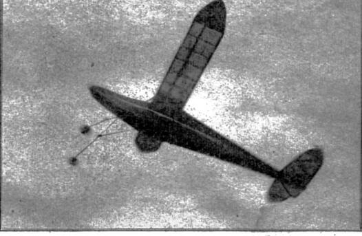
This enlarged shot shows the model still climbing after reachingan
altitude of 400 feet. Rudder is set for wide circling. |

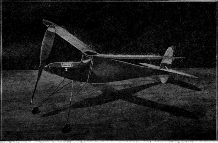
Power packed, this outdoor cabin job averages flights of more thanfive
minutes. The glide is increased with an F-W propeller. |
|

The landing gear is set well forward to absorb
the shock of head-on crashes. |
THIS CABIN JOB was built for two purposes. First, to
give its builder all the fun and pleasure that should be expected from a
well designed ship, and second, to demonstrate to those interested
bystanders that they too can indulge in the sport of model plane flying.
This craft, which is capable of twelve minutes high
time, has won several contests held between two New York high school aero
clubs. And now, without going into any further description of its virtues,
let's start right in by checking our Bill of Materials and begin
fabrication of the powerhouse.
FUSELAGE CONSTRUCTION
OUR BODY, or powerhouse if you choose, is constructed
entirely of 1/8" square longerons, cross braces, and diagonals. The first
step is to draw a full size working plan with the position of the
longerons and compression members drawn in heavier lines.
Pin down the top longeron. Cement the break required
for the cabin roof. The lower longeron is slightly curved and held into
position with the aid of ordinary shirt pins. Pin down the short nose
horizontal piece. Next, cut all the required compression members necessary
and cement each one snugly into position. Apply glue along the joining
surfaces, too. Note that the compression members extending from the lower
longeron to the cabin roof are single lengths. Add the angle of incidence
strip to the top longeron with glue.
After the first side is completed, repeat the
construction procedure for the second side. Both sides are then joined
together by cross braces cut to correct sizes from. 1/8" square hard
balsa. Careful, but definite breaks are made in each frame just in front
of the cabin and at the rear. Add the cross braces at these points first
and cement. The remainder of the braces are added from the rear of the
cabin down to the extreme tail end.
NOSE AND COWLING
FULL SIZE formers for the nose section are given in
Plate 2. Use soft balsa for each one required and cement in their
respective positions designated by the side view stations. The nose piece
is then covered on both sides and top with 1/32" sheet balsa. Use cement
generously along the sides of the compression members and rounded tops of
the formers. Press the sheet wood down firmly and insert small pins part
way into the wood temporarily. Later, they are removed. The cabin windows
and curved windshields are made with thin sheet celluloid.
The nose plug is shaped as required from a hard block
of balsa measuring 1/2" by 1-1/2" by 1-1/2".
After sanding the smooth finish necessary, place the
nose piece flush against the nose and with a pencil, mark from behind the
outlines of the fuselage frame opening against the rear of the nose piece.
Use 1/8" square hard wood cut to the necessary lengths to make the rear
ledge. When dry, fit the nose piece into the nose of the body to test for
a snug fit.
To make the two front hooks, use a pair of half round
nose pliers to shape the fittings out of .024 music wire. Insert firmly as
shown in the side view, and dab with a bit of cement. A notch is cut into
the upper part of the removable nose plug. This is clearly depicted by
both side and top views of the plug on Plate 1. It is made deep enough so
that a rubber strand will rest within it undisturbed. The strand is
knotted into each wire hook and fits diagonally across and into the plug
notch.
LANDING GEAR AND TAIL BOOM
SHAPE THE landing gear legs with the aid of the half
round nose pliers. The main gear has a 5" extension on each side of the
body. The horizontal part is set flush to the fuselage bottom cross brace
and wrapped securely with strong thread and cemented. Be sure the thread
is set to measure 9" across. The rear short wire extension is attached to
the body in the same manner and bound as illustrated. A half curve of wire
is attached between the main extensions and bound as illustrated. Rubber
tired or hard wood wheels may be used depending on the choice. The landing
gear has been designed to withstand the severest bounce. When the lauding
gear is completely set to function, cover the underside of the nose
section with 1/32" sheet. The entire nose is then given three coats of
clear dope with a light sanding after each application is thoroughly
absorbed. The cabin roof also is covered with 1/32" sheet. This piece lies
flat between the longerons -- not on top of the incidence strips.
The side view of the tail boom as well as the
perspective sketch depicts the method in which this removable section is
made. The actual frame is made up of 1/8" square material joined with
compression and cross members. A solid tail block measure to fit, is
cemented snugly into the frame as shown in the rear view perspective on
Plate 3. The rear hook is shaped from .040 music wire, inserted bent again
and pulled tight. Dab cement all about to insure a permanent fixture.
The tail boom is held to the fuselage by means of hooks
shaped from .024 music wire. Eight small hooks are required. Insert each
one into the longeron, above and below and apply a bit of cement. Cover
the section with sheet balsa as required.
The rudder underslung is shaped from 1/8" sheet and
sanded to a streamline. The lower tip is guarded with a strip of 1/32"
square bamboo which is cemented in the position shown. The underslung is
not attached in place until the detachable boom section is paper covered.
WING AND TAIL
WHEN tracing rib number 1, trace it completely
including the leading and trailing edge spar. This insures a true airfoil
section. Next, mark off the positions of the aforementioned spars
including the center spar and cut out with a razor.
Make the first template out of hard balsa slightly
undersized. The pencil line used to obtain its correct curve makes up for
the difference. Cut out the required amount of ribs as well as the last
two wing tip ribs. The break for the dihedral angle is made aft of the
center rib -- or at the position for rib one -- right and left of the
center. Raise the spar tips to 4". Place props at each tip while the
cemented spliced center spar dries.
Proceed in the usual manner of wing layout. Note that
the spar tapers slightly aft of rib 3. Add the leading and trailing edge
spars. Round and taper as required to obtain a true airfoil section. Wing
tips are sanded to shape and cemented well. The center section is covered
above and below with 1/32" sheet.
The construction of the stabilizer is as simple as it
appears. The leading edge which is made of 1/8" by 1/4" balsa is sanded to
obtain a round face. The tips are tapered from l/8" sheet balsa. The cross
pieces and diagonals are cut to proper size from 1/8" square stock and
cemented well. The trailing edge spar is tapered so that the cross
sectional view of the stabilizer appears to be streamlined.
The framework of the rudder is similar to that of the
stabilizer. Cement all joining ends well. The rudder tab may be cut to
shape from either stiff manila paper or thin sheet aluminum. The latter,
however, is more reliable. The tab is inserted into a slit made in the
trailing edge of the rudder and cemented.
COVERING AND DOPING
USE THE BEST grade Jap tissue to do the covering job. Apply the paper in
the conventional manner. Leave a 1/4" margin on the section pattern. The
dope should be a thick but clear variety. Work slowly and pull the paper
tightly so that no wrinkles set in. The balsa covered section of the nose
is also covered with tissue. When fuselage, wing, and tail parts have been
covered, water spray lightly and allow to dry under normal temperature.
The dope is applied with a soft brush. For shrinking,
the dope should be thinned out to a workable consistency. One coat will
probably do the job well enough.
FREE WHEELING PROPELLER
A FREE WHEELING propeller decreases the drag set up by
a stationary one. The simple arrangement shown on Plate 3 is made by
following the sketches illustrated. The prop should be carved from a hard
balsa block. Bend the required shoots as shown, insert and cement. A ball
bearing washer may be placed on the rear of the prop shaft before the rear
loop is closed. This washer gives smoother revs and increases the speed
also.
Check the prop for balance. Apply a few coats of thick
dope on the prop and sand lightly between each coat. Attach the engaging
hook as illustrated and cement where necessary. The prop may be painted
with any colored dope chosen. It also acts as a preservative.
ASSEMBLY AND FLYING
RUBBER LUBRICANT may be made by using green soap
particles mixed with 10 drops of glycerine. Rub this mixture well into the
rubber strands. Afterward, arrange the power strands so that they fit
between the prop shaft and the rear hook. Always keep the rubber clean and
well "lubed."
The stabilizer is cemented flush to the detachable boom
piece. The rudder is cemented upright. Check both surfaces for right angle
alignment. When dry, affix the plug in position and bind to the main
fuselage with small rubber bands. The wing is held to the cabin with
rubber bands. It should be held to the roof snugly but not too tight.
There should be a certain amount of "give" in the event the ship hits any
object.
Counteract warps that have set in by blowing your warm
breath over that portion and twisting it back to its normal shape. Glide
test the ship first. If the "bugs" crop up, more glide testing and short
power flights will bring out the beast or bird in it. Use the rudder tab
for slight turns. Do not increase the twist on the tab more than necessary
to make a gentle turn. Too much rudder on a gentle bank causes slipping.
For longer lasting flights, use a mechanical, winder.
THE END
|
BILL OF MATERIALS
Thirty-six feet 1/8" flat brown rubber for power strands
Twenty-five pieces 1/8" sq. by 36" hard
balsa for fuselage longerons, etc.
Four pieces 1/8" by 1/4" by 36" medium
hard balsa for wing and tail parts
Four sheets Japanese tissue for covering
Three lengths .040 wire for landing gear, etc.
Two pieces 3/16" sq. balsa for wing parts
Two large-faced bushings
One piece 1/16" by 3" by 36" balsa for
wing ribs, etc.
One piece 1/8" by 2" by 36" balsa for wing
and tail parts
One 1/2" by 1-1/2" by 1-1/2" hard balsa
block for nose piece
One 1-1/8" by 1-1/2" by 14" hard balsa
block for propeller
One 1/32" by 3" by 36" balsa sheet for
covering fuselage parts
One length .024 wire for hooks, etc.
Dope, cement, rubber lubricant, sandpaper,
knife, razor, wheels (rubber or wood) celluloid, nose pliers, and
cutters. |
Scanned From April, 1941
Flying Aces


 |