|
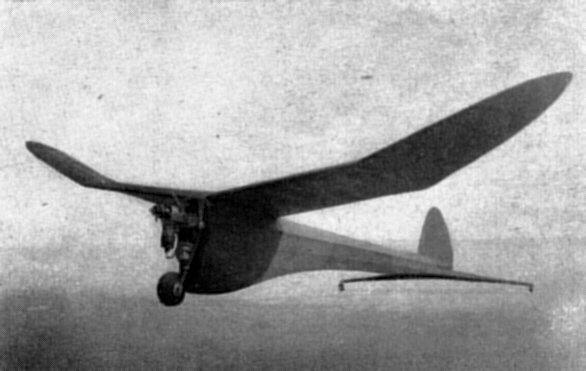
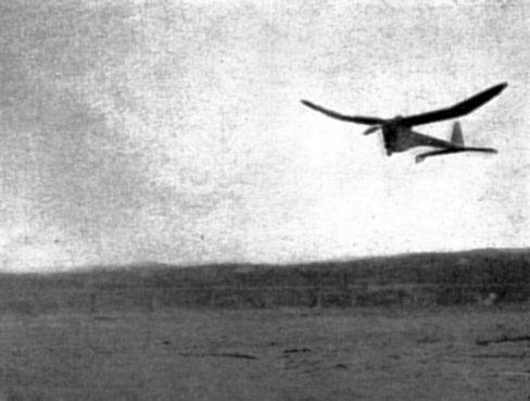
THE RECORD HOUND The ship that set a 1939 N. A. A.
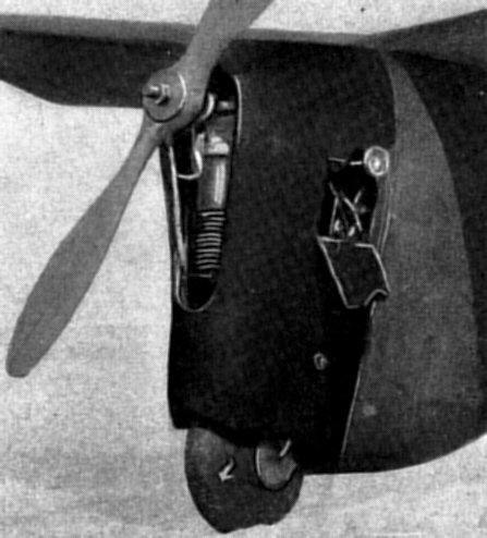
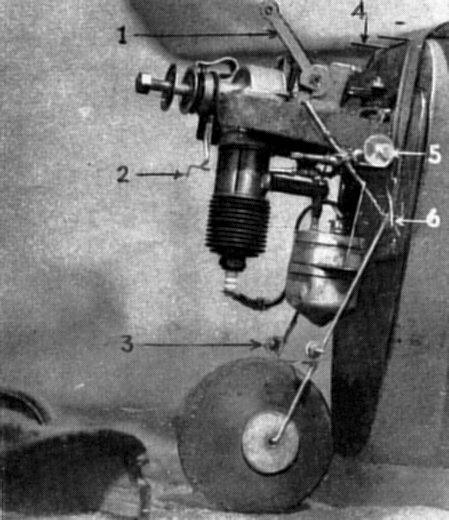
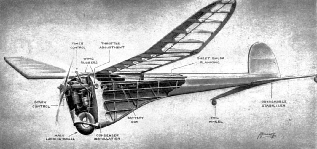
CAREFULLY designed for high performance, easy servicing, and thorough protection of vital parts, this ship is ideal for both contest and sport flying. The single-wheel arrangement has many advantages, chief of which is a great reduction in drag, as the motor and landing gear can be completely housed within the fuselage itself, without exceeding the cross section required by the N. A. A. rule (L ²/100). Though inverted, the engine cannot be damaged by striking an obstruction or nosing over. Last, but not least, a considerable amount of weight can be saved and incorporated in the rest of the structure for greater strength. (Could it be that two ships can be built from one pair of wheels?)The motor unit is easily removable, permitting instant inspection at the field, or bench-testing at home clamped in a vise. A comparatively high thrust line, long tail moment arm, and large stabilizer area aid the ship in assuming and maintaining its own most efficient attitude. Generous polyhedral in the wings and slight anhedral in the tail work for spiral stability: After watching many a juicy spiral, it seems that the tail swings outward, increasing the angle of attack on that portion, helping to rotate the rear of the fuselage. Anhedral in such a situation creates just the opposite effect, producing a righting tendency. The wing area has been kept as small as possible without skimping weight on the motor unit, or exceeding the minimum N. A. A. weight rule of 8 ounces per square foot, to attain the fastest climb and lowest sinking speed possible. These desirable qualities were exhibited by the original at its first contest by flights of 3 minutes, 19 seconds and five minutes, 40 seconds on a 19-second motor run. In calm air the altitude reached with this motor run has been determined to be actually 300 to 400 feet, resulting in a power to glide ratio of over 8 to 1. FRAME CONSTRUCTION The drawings should be enlarged to full size wherever necessary, using the dimension chart and the scale given on the plans. The fuselage is illustrated in four stages of construction on Plate 1. Pin the longerons of 3/16" square hard balsa on the fuselage frame layouts. Fit the crosspieces of 3/16" square and the diagonals of 1/8 x 1/4" in place. See Step1. Remove the upper frame from the plan and mount it above the lower frame, using temporary uprights to maintain the correct heights, as called for by the fuselage dimension chart. See Step 2. Transfer the outline of bulkhead No. 1, given in full size on Plate 3, to a sheet of 3/32" plywood 4 x 10". Use a jig saw to cut it to shape and glue it to the frame, checking the alignment carefully. Prebend the bottom longeron of 3/16" square hard balsa by soaking in water and running it over a soldering iron or other hot metal. When all the moisture has dried out the wood will retain its shape. Insert the longeron in the bulkhead and true it up with temporary uprights cut to the heights given on the chart. Cut the actual uprights to approximate length and cement them against the corners of the longeron, trimming the bottoms when dry. Cover the upper frame sides with 1/16" soft sheet balsa to form a rigid backbone structure. See Step 3. Cement a cap strip of 3/16 x 3/4" soft balsa to the bottom longeron. Stringers of 1/8 x 1/4" medium balsa, fillets of very soft 3/16" sheet, and the tail rest of 1/8" hard sheet are added to complete the fuselage. Anchor the motor unit retainers formed of bicycle spokes to the lower frame with plenty of cement. The rudder outline is made entirely of a 20" length of 1/4" O. D. aluminum tubing. Bend the tubing to the desired outline and hammer it lightly to flatten the section. Split the ends and mount on the fuselage with several coats of cement. This type of rudder can be bent perfectly as the aluminum is "dead" and cannot spring, warp, or be knocked out of adjustment. See Step 4. Attach the wing-and-tail-rubber hooks of .049 wire, using plenty of cement. The wing and stabilizer are of extremely light, yet strong construction. Trace the outline of the trailing edges of 1/4" sheet balsa and shape to a wedge-shaped cross section with knife and sandpaper. Prebend the 1/4"-square leading edges in the same manner as the bottom longeron. Pin the edges to the plans, insert the 1/16" sheet ribs and attach the bamboo tips. Remove the frame, adding the hard balsa spars and the 1/16 x 3/16" rib stiffeners. See wing and stabilizer sketch, Plate 2. Cut the panels apart and install the required dihedrals given on Plate 2, reinforcing the joints with gussets of 1/8" sheet. Cover the leading edge with 1/16 x 3" soft sheet balsa. The stabilizer is built in identical fashion, using the smaller sizes of wood specified. Cut out the center to fit the 3/16" sheet balsa "key" cemented to the fuselage. Be sure this is a good fit and that the key rests on the 3/16"-square diagonals in the stabilizer. See stabilizer mount sketch, Plate 2. Attach a pair of 1"-diameter hardwood tail wheels to the tips by .049 piano-wire fittings. See tail wheel sketch, Plate 2. MOTOR UNIT CONSTRUCTION The motor unit must be made as solidly and accurately as possible to obtain the most consistent performance and trouble-free motor operation. Use thin brads and plenty of cement in assembling. Bind all intersections of metal parts with fine copper wire and solder. Be sure the surfaces to be soldered are perfectly clean and free from oil. Get the metal hot enough to cause the solder to flow, and good joints are guaranteed. Solder of the acid-core variety is simplest to use. The arrangement described was worked out for a Brown D, but may be easily converted to fit any other motor. Cut Bulkhead No. 2 from 3/32" plywood and slide the motor bearers of 3/8 x 3/4 x 12-5/8" bass through it. Bend the landing gear of 3/32" piano wire and fasten it to the mount by a 1/32" sheet aluminum strap clamped between the bulkhead and the crosspiece of 3/8 x 3/4" bass. A similar crosspiece is bradded to the rear of the bulkhead. The landing-gear brace, a single length of 1/16" piano wire, passes across the back of the bulkhead. A block of 1-1/4 x 2-1/4 x 3" hard balsa, hollowed out in back to fit the coil, is cemented to the bulkhead and reinforced along the bottom edge by 1/16" plywood. Fittings A, consisting of 1/8" O. D. brass tubing soldered to a 1/32" sheet brass strap, are attached to the bearers by 1/4" wood screws and soldered to the landing-gear brace. Bolt the engine in place, clamping Fittings B between the crankcase and the bearers, to anchor the upper ends of the landing-gear braces. The needle-valve adaptation for the Brown D illustrated on Plate 2 provides an extension control capable of fine adjustment and not affected by vibration. No dimensions are given, as the best way to assemble the control is by trial. The two washers on either side of the tube must fit snugly to prevent play. The cowling should not be omitted, as it is of great value in keeping the engine free of dirt, also improving the streamlining and the appearance tremendously. The top and bottom of the cowling are made of pairs of 2 x 3 x 4" soft-balsa blocks. Carve them roughly to outside shape, and hollow the inside to clear the motor parts. Cement them lightly to the front bulkhead and plank the middle portion with strips of 3/16 x 3/8" balsa. Finish the cowl with sandpaper. The cowl is held at the top by 1/16" wire pins and tubes, at the front by a hook and eye of .028 wire, and at the bottom by Fittings C. Reinforce the inside with large washers to prevent the bolts from crushing the wood. A small door of thin sheet aluminum is installed and fitted with a rubber band to keep it closed. The battery box shown is for large-size flashlight cells. The box with batteries is held to the bearers with rubber binding. A flight timer is mounted on the 1/16" plywood bracket. Three holes are drilled through Bulkhead No. 2 for the wires, and the motor is wired up in the regular way. It is advisable to varnish the inside of the cowl, the bulkheads, and the motor bearers before mounting the motor and fittings, to oilproof the structure. COVERING AND ASSEMBLY The original ship was covered with red and blue double tissue, cross-grained. This proved much tougher, lighter, and neater than bamboo paper. Apply the first covering with the grain running opposite to the usual way -- chordwise on the wings and up and down on the fuselage. Spray with water but do not dope. Cover the ship again with the grain running as usual -- spanwise on the wings and lengthwise on the fuselage. Spray with water again and apply two or three coats of dope when dry. Slip a hank of four strands of 1/4" rubber, about 12" long, through the wing rubber hook, and attach a large S hook to each end. The wing can be quickly attached by pulling the rubber over the leading edge and hooking the S hooks to the intersection of the landing gear and the landing-gear brace struts. The stabilizer is mounted by an 8" loop of 1/4" rubber passed through a small hole in the rear of the fuselage and onto the stabilizer hooks. FLYING Check the ship to be sure that the surfaces are not -- warped specially unevenly, that the incidence is correct, and the thrust line is not tilted in any way. Check the balance by moving the batteries till the C. G. is located about 4-1/2" from Bulkhead No. 1. Hand-glide the plane, pushing it fairly hard, as it glides at about fifteen miles per hour. Adjust, if necessary, to make a straight and flat glide by warping the rudder or changing the incidence of the wing. Make plenty of tests to make certain it always acts the same. Then bend the rudder slightly -- about 1/4" if measured at the rudder rib -- to circle the model to the right against the torque. Start the motor, get it going to about half speed, set the timer for ten seconds and let the ship R. O. G., pushing it slightly to get it under way. Continue adjustments till a large right circle is made under power and a slightly smaller one on the glide, gradually revving up the motor. Under full power the plane should be launched slightly off the wind, to the right for maximum performance, which -- take it from one who has chased the ship cross-country -- is plenty. Weights
MATERIALS
Scanned From August 1939
|
|||||||||||||||||||||||||||||||||||||||||||||||||||||||||||||||||||||||||||||||||||||||||||||||||||||||||