|
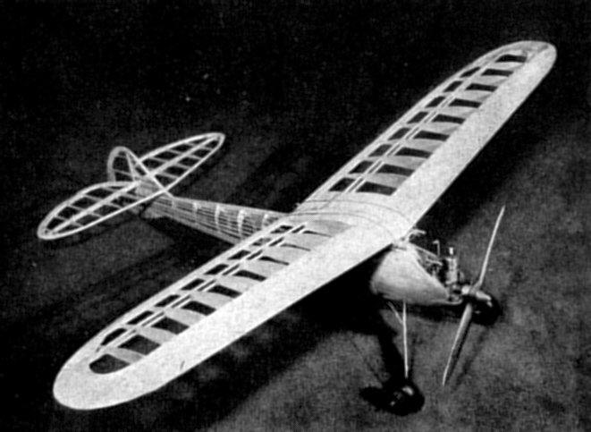
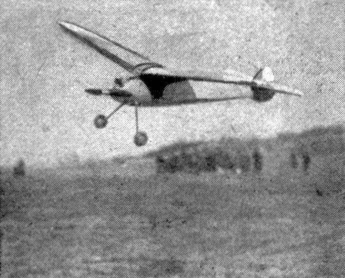
THE PRIVATEER A Class B job that performs By BEN SHERESHAW
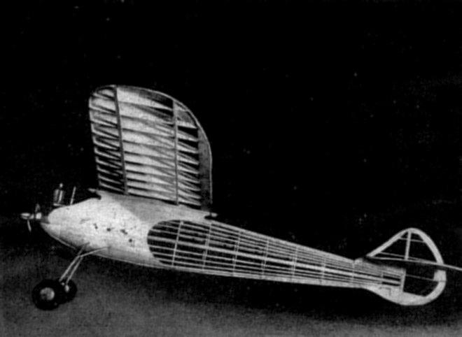
THE advent of the new ruling limiting small-bore motors to models of 225 square inches has created a problem among modelers possessing motors under .2 cubic inches. The Air Trails Privateer, although its wing area is slightly over 300 square inches, by far makes up for the increase in efficiency gained by the added span chord and a proportionately lighter wing loading. Thus it can easily be seen that models of this type and size may be flown efficiently with motors of .2 cubic inches or under. The model is also very adaptable for intermediate motors (.2 to .3 cubic inches inclusive). The glide and climb with these engines can really be described as spectacular. In my observations I have found that the performance of the Air Trails Privateer with a small-bore motor was so excellent that I would feel justified and confident to enter this ship with a small-bore motor in intermediate-class events. FUSELAGE We start construction of the Privateer with the construction of our fuselage bulkheads. The laminated sheets are cemented together first and allowed to dry thoroughly before any of the cutting is attempted. The bulkheads should be cut and sanded smooth to the exact contours as illustrated. Our next step is the cutting of the notches for main stringers or longerons; of which there tire four. Both side longerons are then marked off simultaneously at points where they connect with bulkheads. The side longerons are then inserted into the bulkhead notches together, and are securely cemented in place. Be sure that both longerons possess similar contours. After the check, the lower and upper longerons can next be inserted and cemented in place. The motor bearers and landing gear supports are then slipped into place, and several consecutive coats of cement applied at their junctions with the bulkheads. Allow at least forty-five minutes to elapse between the applications of the cement. Our attention is next focused on the construction of the landing gear on Plate 2. The true length of the landing-gear member is indicated. From this scale a full-size layout is made, over which you bend the landing-gear struts to their proper angle. Both members are made exactly the same, with the exceptions that the axle is incorporated in the front member, and the rear member is bent as illustrated on the side elevation of the ship. It is best to bind both members to the landing-gear supports before completing the final bending of the rear strut. The rear strut is finally bent, bound, and soldered with fine tinned or copper wire. Our next step is the affixing of both the coil anchorage and the battery case. The ship's cross section being brought down to minimum contest requirements allows room for only pen-light cells. It is absolutely necessary to make provisions in this case for booster batteries. Note the booster connections on Plate 1. The ignition system is the very heart of the motor. Therefore give every effort to a painstaking job of wiring. It will surely pay its rewards. The wing mounts are next laminated together, and after being allowed to dry, they are shaped and sanded smoothly as illustrated. Before affixing the wing mounts in place, sew the birch dowels to the wing mounts. The mounts can then be notched to the corresponding thickness of the bulkheads and inserted in place. After checking the alignment of the wing mounts both fore and aft, they can be given several coats of cement. This leaves our fuselage ready for planking. In selecting the planking, be sure to select the proper grade for this purpose. A soft, pulpy balsa is most desirable. You will note that stringers are only used to the rear of the planking, where the fuselage is covered with tissue. It is best to use a tube of cement which is refillable from the bottom for the planking operation. The planks are laid side by side and. are held in place with pins until the cement dries. After all the planks have been applied, the ends may be trimmed off and the entire surface sanded smoothly. The planked portion is covered over with paper, along with the rest of the fuselage. Our nose blocks of 1/2' soft plank can now be cemented in place. Do not attempt to trim until the blocks have thoroughly set. The hatch cover over the ignition unit should be fitted to the fuselage to a snug fit. The hatch is best held in place by rubber bands anchored on the inside of the hatch and fuselage. This tends to snap the hatch in place when pulled out of position. TAIL SURFACES Both tail surfaces should be scaled to full size before attempting any of the construction. All the component parts of both the rudder and tail should be cut out first and then assembled over your full-size layout. Assemble the entire tail unit on the fuselage that is both the rudder and elevator before affixing the leading edges to either surface. Note that the tail skid is embedded in the rudder outline. Because of the extreme thinness of the trailing edges, it is important that they be laminated to resist warpage and dope distortion. Fill in with a soft grade of balsa wherever indicated on the plans. From a standpoint of trim it is of utmost importance if you are using the standard Smith coil pen-light cells and an engine under 3.5 ounces, that you give the elevator three degrees positive incidence. For engines between 3.5 and 4.5 ounces, two degrees will suffice. Finer adjustments can be made with your horizontal trim tabs. The entire tail assembly is covered with a light grade of bamboo tissue and given several coats of dope. Be sure to check against distortion after each coat of dope. WINGS As in the tail assembly, a full-size drawing is required. This should be scaled up accurately and laid out on a level work board. Cut out and notch all the required parts from a good grade of balsa. Note the recess at the leading edge of each rib to accommodate the sheet-balsa covering. It is recommended to those having a limited amount of power available that the sheet covering on the lower surface of the wing be left off. The best general procedure to follow on this type of wing is to lay your lower front and rear spars over their proper locations on the drawing. The ribs should next be inserted over the spars, at the same time keeping an eagle eye on their perpendicular alignment. After the check they can be cemented together. The upper spars are then placed in the rib notches and adhered to the ribs. Be certain to incorporate the proper angle at the butt rib, so that the correct amount of dihedral will result when both panels are put together. Our spars are next boxed to act as surface for the wing joiner, which is shown in full size on Plate 2. The leading edge of 5/32" square balsa, which can be generally stripped from oversized 1/8" medium-hard sheet, is next cemented in place. The, trailing edge, which has been roughly shaped before attachment to the ribs, can next be adhered in place and finished off after the cement has been allowed to dry. The wingtips of bamboo are usually shaped over some hot object. A good method is to shape the tips over an open gas flame. Be sure to keep bamboo far enough away from the flame to prevent charring. Bend the tip a little at a time until it conforms exactly to the full-scale tip. Enough bamboo should be shaped so as to permit the piece to split in two, thus insuring two identical tips. After the tips have been cemented in place, the sheet covering over the leading edge and center section should be cemented in place. Be sure to select the proper grade of wood for this step. The balsa should possess good bending qualities. Before applying the sheet covering to the lower surface, the panels should be cemented together and the plywood wing joiner cemented in place against the boxed spars. Be sure that both panels are aligned to one another. The woodwork should be given a smooth sanding before covering with a light grade of bamboo paper. TEST-FLYING The center of gravity of the Privateer, all ready to fly, should run through thirty percent from the leading edge at half the span. Glide-test the ship from an elevation. Be sure that the nose shows no tendency to come up during the glide. The model may now be given its first power flight. Be sure to set the timer for not more than fifteen seconds for the initial flight. The trim flaps are for minor adjustments only. If the stall or dive is too critical, check the balance and alignment of wing and tail surfaces.
BILL OF MATERIALS Fuselage
Wing
Tail Assembly
Skid and Landing Gear
Motor Plates
Accessories
Scanned From September 1939
|