|
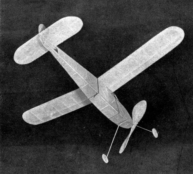
THE FLYABOUT Quickly built and a sure-fire performer, this little
ship
THE first built-up fuselage always presents a variety of problems for the beginner. Usually he has mastered the difficulties of wing and tail construction through making elementary stick designs. Fashioning the built-up fuselage to a true shape with ample strength for carrying the rubber motor causes the most trouble. Therefore, considerable space has been allotted to a detailed description of the fuselage and the steps in its construction. CONSTRUCTION Longerons are the main items in a fuselage structure. (# # 1, 2, 3 and 4). The bottom longerons are continuous from front to rear. The top longerons are broken into three sections. Top and side views of the fuselage are shown full-size. Join the two pages of drawings to make the complete picture. First build two side panels complete with upright and diagonal bracing. The balsa should be pinned directly to the drawing. The two panels can be built at the same time -- one atop the other -- to insure identical shape and therefore a true fuselage. The balsa can be bent to the required shape without moistening or steaming. Use pins to hold in shape while the cement is drying. Do not insert pins through the balsa but along either edge. Joints between the longerons and the braces should be carefully made. Note that a double brace is used at the front of the fuselage (the nosing bears against the fuselage at this point). Allow ample time for the cement to dry before lifting the two halves off the drawing. The best precaution would be letting them dry overnight. At joints the cement has undoubtedly spread over the two panels, joining them together. Separate them by inserting a thin razor blade. The top longerons aft of the cabin window are flat to maintain correct incidence for the wing regardless of its position on the fuselage. But this flat top has more immediate benefits -- serving as a convenient working basis for joining the two side panels. Rest the two panels upside down on a flat board. Square up the sides with a triangle or square. Cement the cross braces in place. Wherever it is necessary to bend the side panels, insert a small straight pin through the longeron and into the cross brace. Cement the joint liberally before pressing together. During the process of joining the two side panels, continually check the shape of the fuselage. Line it up with your eye, stretch a piece of thread from front to rear through the center of the fuselage to make sure both side panels have the same curve, and check the sides with a square; these are a few methods to guarantee true shape. Pin holes through the balsa or other weak spots resulting from too severe bending can be strengthened by coating the wood with cement. Nosing is cut to conform with the shape outlined in the drawing. Its edges should fit flush with the edges of the front of the fuselage. The plug insert (#16) should fit snugly inside the fuselage. Cement #16 to #6. Make sure the two are accurately lined up to insure proper fit of the nosing when the plug is inserted. Insert the bearing eyelet (#9) into the nosing. Rear hook is anchored by inserting it through a piece of sheet metal (# 7, ordinary tin-can metal). The corners of this piece are notched to fit against the longerons. Landing gear is bent from a single piece of piano wire. One end fits up inside the fuselage, where it is cemented to the longerons and the braces. Wheels are slipped on the ends of the gear. Hold the wheels in position by bending the ends of the axles. Covering is applied with the grain of the tissue running lengthwise. (Determine the direction of the grain by tearing the paper -- it will tear along the grain.) The cabin windows are covered with cellophane. A portion of the fuselage back at the rear hook is left uncovered for attaching the rubber motor to the rear hook. Check these details on the photos. Spray the tissue with water, using an ordinary insect spray gun. Allow the tissue to dry thoroughly before doping. Model-supply companies sell prepared dope of the right consistency in a variety of colors. Wing is shown half size in the drawing. This drawing can be reproduced full size by following the dimensions. The curved tip can be drawn by plotting the corresponding points on a piece of paper which has been ruled off into half-inch squares. The full-size wing-rib shape is shown atop the fuselage-at approximately the same position the wing will occupy in actual flights. Cut fifteen ribs to this shape. Build the wing flat and in one piece. The dihedral is added by cutting the edges and spars on each side the center and raising each tip two inches. Cement the joints carefully and allow ample drying time before removing the block supports from underneath the tips. The wing tips are built up from three pieces of flat balsa cemented as shown by the directions of the grain in the drawing. The wing is attached to the fuselage by a rubber band extending around the fuselage and over the top of the wing. Elevator is built flat, using 3/32 " material throughout. Make a full-size layout from the dimensioned drawing and pin the material directly to it. Round off the edges with sandpaper. Cover the elevator on both sides. Spray and dope before cementing it in place atop the rear of the fuselage. Pin to a flat surface to prevent warping. Rudder can be built directly from the drawing. Construction is identical to the elevator. Cement the rudder atop the elevator. Make sure it is set perfectly straight -- that is, in line with the center line of the fuselage. Lower portion of the rudder is a piece of 3/32' sheet balsa cemented to the bottom of the fuselage. Propeller is cut from a balsa block of medium weight. Mark off the block as shown in the drawing. The propeller is the same size as the one used on the stick model presented in the Little Junior in the August issue. If you built this model you'll be able to use the same propeller. However, it is worthwhile practice to carve a new propeller, since this item is usually a weak spot in the beginner's technique. Freewheeling is helpful in giving the model a better glide. It is a simple matter to add it to the model. #14 is a piece of piano wire with a hook bent in one end. The straight end is anchored to the model with two small wire U pieces pressed into the propeller and cemented. Piece #14 engages the loop bent in the end of the shaft (#13) when the rubber is unwinding. The propeller shaft slips out the loop in #14 when the propeller is freewheeling. Rubber motor is six strands of 1/8 x 1/30". This amount should be increased if your model seems underpowered. The fuselage is strong enough for additional strands without excessive twisting. Winder can be used by attaching the loop in the end of the propeller shaft directly to the winder and stretching the motor through the front opening. Hold the model tightly at the rear hook and at the front. Wing position on the fuselage can be changed to accommodate any distribution of weight. Move the wing until the model balances in a normal flying attitude when supported with your fingertips underneath the wing on the spar. If you add additional strands of rubber, check the balance. It will probably be necessary to move the wing back. Naturally, all balancing should be done with the model completely assembled and ready for flying. Wing angle is taken care of by the natural slope of the top of the fuselage. It will not be necessary to insert any blocks of wood underneath the leading or trailing edges. Warp or twist should be taken out of all the surfaces before flying. The wing and the elevator should be true throughout their length. It may be necessary to give the rudder a slight turn to help the model in making turns. Make these adjustments as test flights prove them necessary. BILL OF MATERIALS
Scanned From September
1939 |
|||||||||||||||||||||||||||||||||||||||||||||||||||||||||||||||||||||||||||||||||||||||||||||||