|
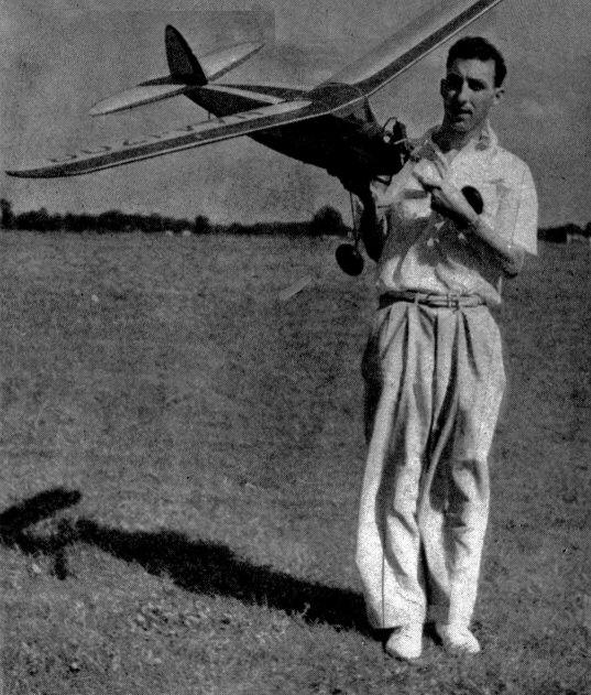
BERRYLOID TROPHY WINNER An unusual gas model distinguished for its beautiful construction, finish, and stability. By HAROLD COOVERT
THE event for the best-finished gas model attracts an impressive line-up of ships. At first glance they all seem to be perfectly finished -- the beautiful finish that most builders dream about but few realize. Each model represents hundreds of hours of work. Two hundred and fifty hours were spent building and finishing the model described in this article. Thoroughness is the main thing. No detail can be neglected. Each individual item must be given careful attention, since every part contributes to the appearance of the finished model. This model is a successful flier and is worth the investment of a good finish. With a little careful judgment in flying, there is no reason why the finish should be marred by crack-ups and subsequent repairs. The instructions for finishing can readily be applied to any model. Or if you're more interested in flying than beautifying a model, this design certainly rates attention, since it earned the title of a successful gas model before it took additional honors for the best finish. FUSELAGE It is a practice of most model builders to get the hardest part of the model finished first, so general instructions will follow. For the fuselage, a full-size side view should be laid out on wrapping paper. Notice that the dimensions are given to the reference line. The 1/4" square longerons are pinned to the drawing to hold them firmly in place while the cement is drying. The upright pieces are also cut to the proper length from 1/4" square balsa. The diagonal pieces are cut from 1/8" x 1/4" stock. The 1/8" fillets, part H and the fairing piece below are cemented so as to be flush with the outside when completed. When side frames are thoroughly dry, the cross-members are cut from 1/4" square and cemented in place. It is best to start at the windshield and work back, being sure to keep the fuselage lined up properly. Parts F and G are cut from 1/8" flat stock. They are 1/4" wide at the windows, tapering back to 1/8". Formers B, C and D are cut from 1/8" stock. They are shown full size on the pattern sheet. Refer to Section A-A for the next step. 1/8 x 1/4" strip stock is used full length for this. Cement in place as shown. Sand to cross section given. These should not be rounded off where the wing rests on the fuselage. The 3/16" dowel window braces are cut and placed. Former A and E are cut from 1/4" three-ply fir (full-size patterns). If the swiveling tail wheel is used, part N is cut from 1/4" balsa stock. Drill the four 3/32" holes before cementing in place. Former E is not cemented in place until the landing gear is assembled to fuselage. The motor mount pieces are cut and drilled as designated on the drawing, as well as the 1/4" V-piece at side of motor mounts. The trapdoor is cut from 1/4" flat balsa and lightened as shown. It should be strengthened with 1/8 x 1/4" strips of bass wood on the bottom as shown in dotted lines. This is not necessary if a fine finish is not desired. Aluminum tubing, 1/16" outside diameter, is sunk into the leading edge of door, and pieces of L-shaped .032" music wire form the complete hinge. It is held is place with a pin on each side at the rear. The cowl is cut from 1/32" three-ply birch. A full-size pattern is given. Do not attach at this time. LANDING GEAR The main part of the landing gear is formed from 1/8" music wire. Study the drawings before doing any actual work. It is a good plan to make a full-size layout to assure a good job. The V strengthening piece, front view, is bent from 1/16" music wire. When all three pieces are finished, they are bound tightly with #24 soft iron wire and soldered well. Add the small circular pieces, .032" music wire, at the top of the front strut which holds the rubber from slipping down. When finished, it is attached to the fuselage by wrapping with string and cementing generously. Proceed to cement bulkhead E in place. The drawing on the tail wheel is self-explanatory, except that a piece of inner tube can be put in back of the main assembly C. This greatly helps the shock-absorbing effect. STABILIZER The ribs are drawn out first to conform to the shape given in the full-size pattern drawing. The spars are cut from 1/8" flat stock to the dimensions given on the drawing. The trailing edge is cut from 1/4" flat stock. If 2"-wide stock is used it will have a splice as shown on the drawing. Let dry thoroughly before sanding to the given shape. The center section is covered with 1/16" sheet on both sides. Notice the .032" music wire hooks to hold the stabilizer in place. They circle the spars and are cemented well. Sand the leading edge to the section shown on the side view. The fillets that appear in front are cut from 1/8" stock. Sand flush to the rib curve. Note the slot in the center section to receive the rudder spar. Ribs #1, 2 and 3 are cut 1/16" smaller on both sides to allow for the sheet covering. RUDDER The leading edge is laminated from two pieces of 1/4" medium balsa. A full size pattern of rib #3 is given. Cut the others to conform to this. Ribs # 1 and 2 are cut 1/16" under size on both sides to allow for the sheet covering. The trailing edge is cut from 1/4" stock. It is best to shape the trailing edge before assembling. When the rudder is completed it is sanded smooth and cemented -- use a generous amount -- to the stabilizer. WING The first step is to cut the pattern (#2) and paste it to thin cardboard. Twenty-four of these ribs are required, but it must be noted that the spar slots are located differently on each rib. A full-size layout would save a lot of time in this operation. The leading edge is 1/4" square hard balsa set in at 90 degrees. The trailing edge is two pieces of 1/16 x 2" soft balsa. Note "Detail of Wing at Center" for this step. The tip is laminated up of 1/4" soft balsa, cut and sanded to shape before being assembled. Assembly itself starts with the construction of the spars. Note how the joints are made with an addition of plywood on each side for added strength. These joints should be cemented well. The front spar is constructed from 1/8 x 1", while the back, is made from 1/8 x 1/2" hard balsa. The ribs are cemented in place on one side at a time, pinning the spars in place to assure proper alignment. The 1/4" leading edge is followed by the trailing edge. It may be necessary to pin each rib to the trailing edge until the cement dries. When dry, proceed with the opposite side, followed by the center-section ribs, which are cut clear through, 1/32" wider on each side for the extra thickness of the spars at this point. The 1/16" balsa covering is cemented in place with the grain running perpendicular to the ribs. Note detail "Making the Leading Edge" for this step. Tip ribs #3 and 4 are given full size. Notice from front view that top of wing is straight. The tips of the spars have to be built up as shown to connect up to the tip. Cap strips of 1/16 X 3/32" are cemented top and bottom of each rib. Sand the entire structure smooth. This is very necessary for a good covering job, as every imperfection shows up when doping the model. Particular care should be given to cemented joints. BATTERIES AND IGNITION SYSTEM Batteries are carried in an adjustable battery box. The details are shown with dimensions. Notice that there are two clips on one end of the box and one on the opposite end on the outside. The brass strip makes the connection on the inside. The plus end of the battery rests against this strip. When the batteries are in place in the plane there is nothing except a crack-up that can move them. The slide itself is constructed from a piece of 1/8 x 3 x 12" balsa stock strengthened on the bottom with pieces of 1/8 x 1/2", the grain running perpendicular to the slide. The side view shows the proper location of the slide. After the location is determined for the box it should be clearly marked. When wiring up the model, the wires to the box will have to be made long enough to allow sliding the box in at the rear. FINISH The finishing of the model is a very interesting part, but one that requires a great deal of patience and time. The model is covered with silk with a color scheme of yellow with brown trimming. A 1/32"-wide pin stripe outlines the colors, setting it off very nicely. A word should be said about working conditions. Try to do the finishing in a dry room of about seventy degrees temperature, and above all, dust-free. A cold, damp room will retard proper drying and tend to cause "blushing" (turning white). As balsa wood is very easy to sand, the entire model should be carefully gone over, being sure that there are no uneven places. These show up very prominently and often spoil an otherwise beautiful model. No. 400A wet or dry sandpaper was used for the final going-over. See that your brushes are of good quality. A 3/8" and 1/2" soft camel hair brush was used. All the finish is applied with the brush. A good workman can do no better work than his tools will allow. Berryloid finishes were used throughout. The silk should be applied to the framework with heavy dope, being careful to keep all wrinkles out and keeping it taut. The covering was not water-doped, but given a very thin coat of clear dope. Let this dry thoroughly before continuing. This is followed by five or six coats of clear, or until all of the pores, which appear when doping silk, are covered. After drying for at least six hours it is sanded lightly with No. 400A sandpaper. Do not rub very hard over the ribs and edges of the framework, as it is very easy to go through, The dope should be thinned about fifty per cent for this operation. The pigmented dope is thinned to about one part thinner to two parts dope. Twelve coats were applied, sanding very lightly between every other coat. The last coat is thinned fifty per cent and flowed on, being careful not to cause any runs. Leave to dry for at least twenty-four hours. The last coat is rubbed with Berryloid Superfine Rubbing Compound. Caution must be used when rubbing over ribs and sharp corners so as not to go through the silk covering. A little practice will acquaint you with its use. After the surface is wiped free of all dirt and oil which the compound makes, the white pin stripe is applied. A draftsman's ruling pen is used, leaving the dope fairly heavy. A straight edge and celluloid curves are used as a guide. The final operation is a rubdown with Simoniz, which gives the finish a very high luster. FLYING For ordinary flying, the Brown junior motor should be set at about one-third throttle. If more power is used, more down-thrust will have to be used to prevent stalling. Two degrees' positive incidence is used in the wing, with the tail surfaces neutral. Up to date the model has had twenty flights, all of which were very successful, seven being made before the Nationals. A word about balance. The battery box is shifted back and forth until the nose is slightly heavy. This may be determined by holding the model under the wings, halfway out and third way back, using your index finger. Unless you use a timer on your plane, don't fill the gas tank more than enough to run the motor about one minute. It is not advisable to test-fly your model on a windy day, as it is too hard to make adjustments and very dangerous for the model. Take it easy, work very carefully, and you will have a model worth your efforts. Happy landings!
MATERIAL LIST
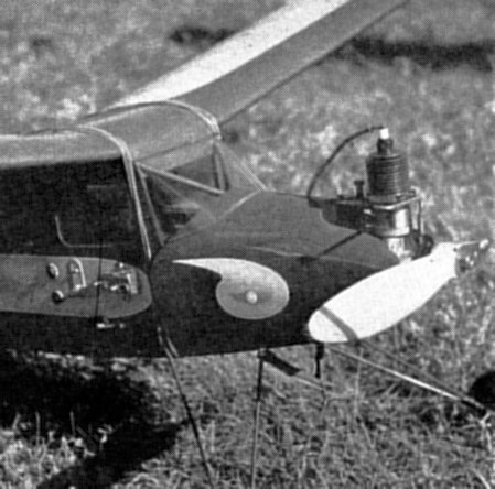
Material list is not given for the one-bladed propeller, as it is an optional feature. The drawing gives all the necessary dimensions and the kind of material. The one-bladed prop proved itself quite successful. Scanned From November, 1938
|