|
Completing this graceful and proven gas job - Part II. By Carl Goldberg
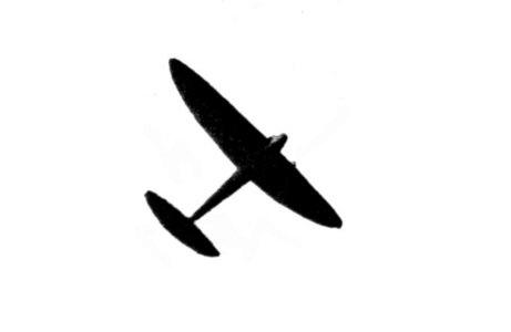
Multispar construction is used in the wing and tail surfaces. This system makes a strong, lightweight wing -- the completed wing weighed 20 ounces. Practically any portion could have been destroyed without affecting the strength of the wing as a. whole. While this construction is not difficult, it is tedious -- there being over 1,100 individual pieces in the wing alone. WING CONSTRUCTION Specifications of the wing are: span 10'; root chord 20"; aspect ratio 7-2/3 to 1; area 13' square; dihedral 10" under each tip; double elliptical taper; original Goldberg section; and 2° incidence. Figure 2 shows the method of laying out double elliptical taper. Follow this method for making a full-size wing layout. From this layout you can determine rib lengths, leading and trailing edge curves and a variety of other details available only from a full-size drawing. Full-size ribs are given in Figure 1. Cut a template to the shape of the top camber and another template to the shape of the bottom. Slice the top and bottom portions from 1/8" flat balsa to a width of 1/8". Cut off at the trailing edge as necessary to fit ribs to taper of wing. Procedure of the work is as follows. Pin the pre-bent leading edge, trailing edge, and the tip pieces -- minus reed -- to the drawing. Next add the top ribs. Stand the wing on the root rib and add the bottom rib. Cement spars in position to the ribs, add rib bracing and finally the diagonal bracing between the ribs. The original wing was made in two separate halves and joined before covering. However, the ten-foot span made it difficult to carry it from place to place. A device whereby the wing could be folded in the center would be helpful. A diameter reed of 3/16" is countersunk halfway into the balsa wing tips. Taper the thickness of the trailing edge to match the varying depth of the wing camber. Cement the two halves of the wing together, matching the ends of the spars, leading and trailing edges. Add the 1/16" sheet covering to the top and bottom of the center and the tips. Cover the entire wing with heavy bamboo paper. Two coats of thinned clear dope are then brushed on the covering, followed by two coats of thinned yellow. WING MOUNT This method of mounting the wing was worked out several years ago. It permits the wing to detach from the mount upon any heavy impact, thus saving it from damage. The mount is shown in Figure 4. The framework is built exactly like the upper rudder with the same specifications for material and the same section. The first step is to cement ten pieces of 1/8 x 2 x 4" to the bottom of each half of the wing. These pieces form the platform in which the wing rests. It must fit the bottom surface of the wing snugly.
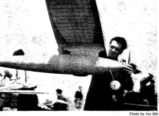
Carl Goldberg holds the Valkyrie aloft to display the
multispar wing and The platform is supported by a balsa backbone 1/4 x 1 x 20" cut to fit the undercamber of the wing and cemented to the bottom of the platform. Build up the rudderlike framework and attach it to the platform and the backbone. Note that the bottom rib of this framework must fit the top of the fuselage. 3/8" incidence is used for the 12" chord, which gives 5/8" for the 20" chord of the wing. Figure 4 is dimensioned to include this incidence. However, if you didn't follow the drawings of the fuselage closely, you had better check up on the incidence, since Figure 4 is dimensioned from the fuselage data given last month. ATTACHING WING MOUNT The model should be nearly completed and assembled before attaching the wing mount. In this way the location call be determined, depending on the center of gravity location, which should fall at a point 45% or 9 inches back from the leading edge of the wing. Holes are drilled through the skin and the wing mount floor (inside the fuselage). Insert the ends of the spars, leading and trailing edges with the bottom rib resting atop the fuselage. Secure with cement to the wing mount platform and the skin. Cover the wing mount with 1/16" sheet balsa. Add soft balsa fillet-blocks to the corners and sand with rough sandpaper wrapped around a circular block. Finish off with fine sandpaper. The photos show the fillets clearly. Bend and insert wire attachment hooks. The wing is held to the mount by rubber bands passing around the front fitting, over the top-center of the wing and fastening to the rear hook. STABILIZER Specifications of the wing are: span 4':12" root-chord; area 3' square; double elliptical taper; original Goldberg section; incidence 1/2° negative; and area equal to 23%, of the wing. The stabilizer is laid out exactly the same as the wing. That is the chord and span dimensions of the stabilizer are substituted in Figure 2. As in the case of the wing, a full-size layout is essential for good results. The method of construction and the steps in the procedure are similar to those used in the wing. Build in two halves, complete except for covering, and insert the end, of the spars through holes drilled in the skin covering at the rear of the fuselage. Coat the spar ends liberally with cement before inserting them. Also cement the end rib of each half of the stabilizer to the side of the fuselage. Add 1/32 medium sheet balsa to the top and bottom of each half of the stabilizer -- as indicated in Figure 5. Cover with bamboo tissue and dope first with thin clear dope, followed by one or two coats of thinned yellow. RUDDER Specifications of the rudder are: upper rudder 9" high, 12" root chord ; aluminum tab; lower rudder 4" high, 12" root chord; sheeted with 1/16" balsa; multispar construction; streamline section; area equal to 6% of the wing area. Figure 6 is the drawing of the upper and lower rudders. The upper is a double elliptical taper -- the same method used in laying out full-size shape as in the wing and stabilizer. The lower rudder shape is shown in greatly reduced size in Figure 6. However, the drawing is accurately made to the indicated scale and the essential points have been dimensioned. Draw up your full-size outline from this information. The two portions of the rudder are made separately and added to the top and bottom of the fuselage in the same way its the stabilizer. Insert the cement-coated ends of the spars and edges through holes in (the skin covering. Also cement the end ribs to the outside surface of the fuselage. The movable rear portion of the upper rudder is a piece of .020 half-hard aluminum. The tab is piano wire hinged to the trailing edge of the rudder. Alternate portions of the rudder and the tab are cut away to, form the type of joint indicated in Figure 6. The edges of the aluminum are rolled to as small a radius as possible and a piece of piano wire inserted. The wire is secured to the top and bottom of the rudder and at two intermediate points. Movement of the tab should preferably be stiff to hold any desired setting. 1/16" sheet balsa covering is added to the lower rudder. 3/16" diameter reed is countersunk halfway into the lower outside edge to protect the balsa from wear. The upper rudder is covered with bamboo tissue. Directional stability of the model was good despite the reduction in rudder area to about 6%. And the small, well-shaped rudder did much to improve the appearance of the model. FINISHING The attractiveness of the model depends on the time and attention given to finishing. The balsa skin of the fuselage should be doped and then rubbed smooth with sandpaper, the procedure being repeated until glossy smooth. Fillets should be carefully shaped and then finished to match the fuselage. Any irregularities in the surface should be filled with sawdust and cement or a similar mixture. FLYING ADJUSTMENTS A summary of adjustments includes the following items. Zero-zero setting of the thrust line. No offset thrust of any amount was used. Center of gravity at a point 45% or 9" back from the leading edge of the wing. Wing incidence was 2°. This setting is referred to the center line of the fuselage (thrust line) and is measured by raising the leading edge 5/8" above the trailing edge. A straight edge, held across the bottom surface of the wing, is taken as the chord line. (The wing being at zero incidence when the straight edge is horizontal or parallel to the center line of the fuselage.) Elevator incidence is 1/2° negative incidence. Measure the angle in the same way as that of the wing. 1/2° negative is equivalent to lowering the leading edge 1/8" below the trailing edge. Unfortunately, there was no Valkyrie entered in the recent national meet in Detroit. Goldberg didn't have time to build a duplicate of the original Valkyrie which was lost in Canada last year. The original model was loaded 5.85 ounces per square foot. This could readily have been raised to 8 ounces to meet this year's requirements without any decrease in flying and soaring characteristics. Goldberg graciously credits fellow modelers for their help and advice in completing the enormous task of designing and building the Valkyrie. Thanks go to Sidney Axelrod, Bill Gough, Len Elgenson, Gerald Ritzenthaler, Leon Klesman, Pete Vacco, and others in the Chicago group. MATERIAL REQUIRED Wing
Wing Mount
Stabilizer
Rudder
Additional Items
Scanned From October, 1938
|