|
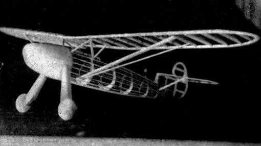
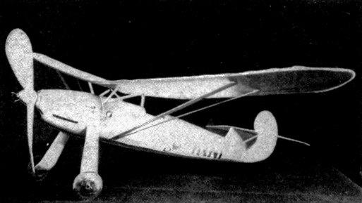
FOCKE - WULF STOSSER Complete plans and directions for building a high performance miniature of a world-famous German sportster. By PAUL PLECAN and ROGER HAMMER
Any model builder who has looked for a model that was one hundred percent scale and yet stable enough for flight with the scale tail surfaces, will know how rare such a model is. The Focke-Wulf Stosser fills the bill. Scale outlines of the tail surfaces are shown on the plans, as they have been proven to be of sufficient size for a stable flying model. Used mainly for training purposes, the Stosser mounts an Argus inverted V-6 engine which gives it a top speed of 167 miles per hour. The cruising speed is 154 m.p.h., and the landing speed is 56 m.p.h. The Stosser is a familiar sight to many, as it was brought over by Gerd Acheglis for participation in the acrobatic events at the past few National Air Races. The plans reproduced on the next few pages will produce an accurate model of Gerd Acheglis' original ship, that is, if they are followed explicitly. FUSELAGE Since the fuselage is the toughest part, let us tackle it first. Cut out the master stringers and formers. Before proceeding any further, note that there are two notches in the tail end of each side master stringer. Mark off the positions of all the formers on each master stringer, and cut the grooves in the formers. After assembling, check the whole unit for alignment, as some of the master stringers are bound to be slightly warped. The tail hook -- tail skid may be bent to shape and cemented in place now, as there are no stringers to impede your work. After this has been done, cement the 1/16" square stringers in their respective places. .Check again for alignment, and correct if any warps are apparent. Trace the side view of the engine nacelle (or cowl) on a soft balsa block measuring 2 x 2-1/8 x 3". After shaping to conform with the side view, repeat the process for the top view. Cut down the outside of the cowl to the correct cross-section and sand until smooth. Apply dope (wood filler is better for this if it is available) and sand very smooth when dry. The cowl should be cut in half now, and hollowed out to the thicknesses shown on the plans. Cement together, and conceal the saw mark where the cowl was cut in half by applying successive coats of dope and sanding. The nose plug can also be made at this time, and care should be taken to have it fit quite snugly, as adjustments are easier this way. The front portion should be of very hard balsa, as it will take a lot of abuse. Cement the two parts together and add the two washers. (Note the slight right thrust and larger amount of down thrust.) The landing-gear struts should be bent to shape and cemented to the fuselage. The front wire strut is bent back at the bottom to provide an axle for the 1-1/4" balsa wheel. Cut the balsa strut to the right size and insert between the two wire struts, cementing well. The fuselage covering maybe applied now, in small strips. Do not forget to add piece "A" to the tops of formers 6 and 7, as it supports the stabilizer. The fillet block in front of former 6 should be carved now and cemented in place, and the whole unit doped, since this will be harder when all the struts and details have been added. The fuselage is doped silver with two or three coats of dope, and set aside. After it has dried well, lettering and exhaust stacks may be added. TAIL SURFACES The tail surfaces are made in a way that provides extreme flexibility and consequently easier adjustments. The rudder and stabilizer are broth cut from 1/16 x 3" sheet, and care is taken to have the grain running the right way, as shown on the plans. After the stabilizer has been covered, the small fins shown in the side view should be cemented on. The rudder should also be covered, and both the parts doped silver. The easiest way of duplicating the insignia shown on the rudder is as follows: Dope a red band around the rudder and set aside. While the red dope is drying, cut a small circle from white bond paper. On this paper draw the swastika and fill in with black india ink. Cement the paper circle on the middle of the red band-and there you are, a very neat job done with a minimum of effort and time. WING Cut the ribs out of 1/16" sheet, making two of each, except #3, of which fourteen should be cut out. The 1/16" thick wing spar should be cut to the depths shown by the rib notches. Assemble the wing on a flat surface, such as a drawing board, and cement the parts together. Break the leading and trailing edges at the proper points, set at the right angle to secure 1-1/4" dihedral, and cement. The whole wing can be covered now and doped silver. Do not forget to draw the letters on the wing at this point, as it will be very hard to do the lettering if the struts are in place. ASSEMBLING The easiest way to get the wing at the right incidence and position is to cut a small piece of scrap sheet to the outline formed by the bottom of the wing and the top of the fuselage. Pin this jig on the fuselage and then pin the wing to the top of it. Fit the struts by the "cut and try" method, and after they have been cut to the right size and sanded to a streamlined shape, cement them in place. After you have fitted all the struts, take the pins out of the jig and remove it. Add slight amounts of cement to the joints between the struts and the wing until a small fillet forms. This will not only enhance the appearance, but will duplicate the streamlined fairings on the original ship. Cement the stabilizer onto part "A," and fit the rudder so that it will turn the model to the right when gliding. Cut the propeller from a medium block, of the size shown on the plan, and carve so that it has about 3/32" or 1/8" under-camber. Add the two half cones to the side of the prop and then the top cone. The freewheeling shown may be used, but this is entirely up to the model builder. Add the small details, such as the step on the left side of the ship and the "N" strut between the main struts and the bottom of the wing. The aileron and rudder outlines can be simulated with a narrow strip of black tissue cemented or doped over the finished wing. Since the entire model will weigh between .7 and .9 ounce (depending on the materials used, of course), four strands of 1/8" flat rubber will do for normal flight. When lubricated, with an inch of slack, the rubber can be wound up to 750 turns without fear of breakage. If you are in doubt as to the freshness of the rubber, however, do not use more than 600 turns. Testing can best be accomplished on a grass-covered field or lawn, but if you are a "city slicker" you'll have to R.O.G. your model with successively larger amounts of turns in it for adjustments. Scanned From November 1938
|