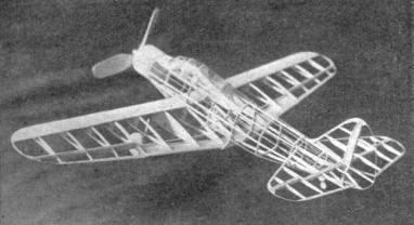
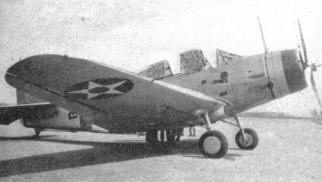
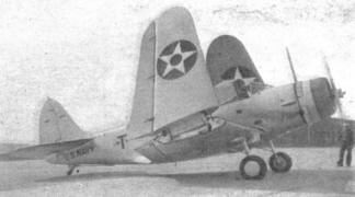
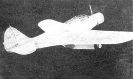
TORPEDO PLANE Plans for a realistic flying scale model of the formidable Douglas TBD-1 BY Alan D. Booton
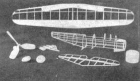
THE TBD-1 is a torpedo-bomber designed for aircraft carrier service. Larger than the scout or pursuit job, the TBD-1 has wings of unique design, folding about midway on each span, conserving space, which is limited on carriers. An exceptionally high speed is obtained from the 850 h.p. Twin Wasp. The folding wings, flaps, and realistic movable controls have been included in the model without a noticeable increase in weight, and the accurate design has further possibilities where more detail is desired. The simple method of placing the wing eliminates the tedious line-up job. FUSELAGE The formers can all be cut from a sheet 4 x 6" of 1/16" balsa plywood. Use waxed paper between drawing and assemblies. Build the left side of the fuselage on the drawing and then build the right half directly to the left half. Begin by pinning corresponding top and bottom parts to the drawing and then cement the formers to their respective stations. It will be noticed there is nothing to cement to at the top from A to E, so a 1/16" temporary strip is cemented above the former spacers from A to D, then up to E to aid assembly. The plain rib at the bottom may be lightly cemented to, for the joints are easily separated with a razor blade at the proper time. Add the balsa side longerons. Prebend them to avoid a sprung fuselage. Remove from board and duplicate the first steps right on the assembled half, then add the bamboo stringers, rear hook. WING AND LANDING GEAR Build the wing as a unit. Due to the curve of the ribs, the bottom spars must be blocked up proportionately from root to tips to keep the incidence even. Do not cut the ribs for the ailerons until the wing is assembled, then slice out for the aileron spars and fit the spars in. Remove the top spar between the #2 ribs, then crack all spars at #2 ribs and block the tips up 1-7/8". Replace the piece of top spar and cement the cracked spars. When dry, remove and install the flaps. Cement the M pieces between ribs 3 and 4 and install the landing gear, which is explained on the drawing. TAIL SURFACES Build the tail surfaces out of plain unshaped stock, and when complete sand them to the tapered streamlined shapes. This method is much easier and more accurate than precutting all ribs before assembly. The hinges can be copper or soft iron wire. The lower part of the rudder has to be added on to, to conform to the last former. The stabilizer should be made as a unit. PROPELLER AND COWL Carve and hollow the cowl from a soft block and cement in the retainer disc. Make the nose plug to fit snugly in the hole. Bevel the three propeller blocks as shown on the drawing and prime the bevels copiously with cement. Before the priming has fully dried, add more cement and clamp them together with pins, on a flat surface. After drying several hours, blank and carve each blade in the accepted manner. Dope and sand to a glossy finish. The balance may be obtained by adding a coat of dope to the light blade. Assemble the prop, nose plug, washers, and prop shaft. COMPLETING THE MODEL Cover the leading edge of the wing with 1/64" sheet balsa and the remainder with silver tissue. Form the celluloid cockpit cover to fit well, then remove it and cover as much of the fuselage as possible. Cover the tail surfaces with silver tissue. Install the wing in its place under the fuselage. Slice through formers H and I on lines directly over and between the second top longerons. The top of the fuselage can then be raised enough to install the stabilizer. Cement the parts back together and cement the vertical tail on. Check repeatedly to see that the surfaces are in correct alignment. Fashion a dummy tail wheel and deck hook and cement them in place. Fillet the tail surfaces and wing with tissue. Cement the cowling on, the cockpit cover and radio antenna masts. Make the panel frames on the cover by doping on narrow strips of silver tissue. Spray the tissue lightly with water and when dry, if the model is streaky, coat the surfaces with a thin coat of silver dope. The wheels and inside the cowl are black. The lettering is black. Add any remaining detail that is desired. Power the model with three loops of 1/8" flat rubber. The loops are tied at both ends, the special "S" look at the rear. The motor is engaged to the rear hook by "fishing." With this model, first tests should be made by letting it take off under its own power, making adjustments between flights until a steep left-hand climbing turn is accomplished. LIST OF MATERIALS Blocks
Sheet
Strips
Miscellaneous
Scanned From August 1938
|