|
The Stinson Reliant SR-6
By William Winter
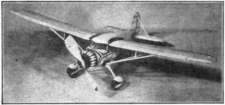
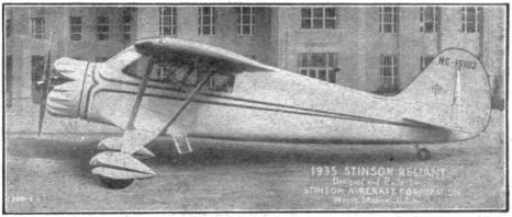
THIS latest Reliant, like its predecessors, vaunts beauty, strength, and enduring performance. Indeed the Reliant type has been so successful that more than 260 of them have been sold since June, 1933. Moreover, the Lycoming motor has been used in more than 600 Stinsons, and it is estimated that this faithful power plant has a record of 80,000,000 miles! With the 260 h.p. motor the SR-6 cruises at 133 m.p.h. The ship comes equipped with Smith controllable propeller, dual ignition magneto and multiple disc wheel brakes, besides other more conventional fixtures. In addition to the pilot the plane carries three passengers, 60 gallons of gas, 5 gallons of oil, baggage, and 80 lbs. of special equipment. With this load, the Stinson climbs 875 ft. per min., has a range of 500 miles, and lands in 225 ft. with the aid of wing flaps. Our model, like all Stinsons, can be relied on to give abnormally long flights, and its beauty is only matched by its stability in flight. FUSELAGE NOTE before beginning construction that a full list of materials is given at the close of this article. Incidentally, if you do not wish to mar your magazine, make tracings of the plans on any semi-transparent paper. First, fasten the longerons of 3/32" to the bench on top of the side layouts. Cut all the cross pieces shown in that plan and cement them in place. When dry, remove the finished sides from the form and separate them from each other with a double edged razor blade. Cut all the cross pieces shown in the top view, and by the use of pins to hold the work in position connect the two sides at the widest points. When dry, fasten the remaining cross pieces in place and carefully check the alignment. It will be noted that the rudder post of 1/8" by 3/16" is attached so that its greatest dimension is crosswise on the fuselage. It is best to bend the rear hook of .028 music wire and to fasten it in position at this stage of construction. It is necessary to crack and cement the longerons at the front of the fuselage, as shown in the top view, to attain the necessary shape. All fairing formers are cut from 1/32" sheet balsa. The notches should not be cut until the formers are in position and you are ready to fasten the stringers in place. All the formers are marked as follows: Top - T, Side - S, and Bottom - B. After the formers have been cut to shape, those on the bottom should be glued in place. The stringers of 1/16" sq. should now be attached at the positions shown. This order of construction is followed so that the stringers will not be "wavy" in appearance. The top fairing is done in like manner. The side fairing runs back as far as the third cross piece. T1, B1, and S1 form a perfect circle. The short upper stringers between T1 and T2 are inserted in place and require no notches. There are two doors, one on each side of the body. Block E is cut to shape from soft, balsa, sanded and cemented flush with the front edges of T4. To cover, use separate pieces of tissue for the flat portion of each side. Narrow strips of tissue will have to be cut so that the fairing may be covered in a ship-shape manner. As each strip is doped in place, the edges will have to be repeatedly trimmed. The finished covering is evenly sprayed and given a smooth coat of clear dope. The windows are covered with cellophane. The edges of the windows and of the doors are painted black with a fine brush. LANDING GEAR AND TAIL WHEEL THE fillet blocks shown on the front and side views are cut to shape from soft balsa 3/4" by 7/8" by 2-1/4" and sanded smooth. When finished, glue them firmly in place as designated. Note the holes made to receive the bamboo pins. The struts are cut to the dimensions required and streamlined from blocks of hard balsa 3/8" by 1-3/8" by 3-7/8". Cut the holes shown on the detail for the bamboo pegs. The pants are built up in three layers. The outside ones are 3/16" sheet. The center one is a block 2-15/16" by 9/16" by 1-3/16". The shaping is not done until the three plies have been firmly glued up. The 1-1/2" wheels rotate on short .028 axles and are mounted in the pants at the position shown. The struts are fastened to the pants and to the fillets with bamboo pins and with cement. The joint at the pants is braced with two pieces of .014 music wire as shown and bound with thread. The complete joint is evenly glued. The joint at the fillet is braced in like manner but with one piece of wire. Streamline a small piece of balsa of the size shown in the tail wheel mounting (side view) and cement it to the fuselage at B9. The 5/8" wheel is mounted on a small piece of .014 wire. This wire runs upward through the small balsa piece and is secured in the 1/8" by 1/4" that forms the hook mounting. TAIL ASSEMBLY THE stabilizer halves and the rudder are laid out directly on the plans or tracings. Provision is made for movable controls - if they are desired. Sheet aluminum of a very light gauge is used for hinges, serving the purpose well and avoiding tedious work. The spars are 1/16" by 3/16". The cross pieces are all cut from 1/32" sheet using the patterns given. The edges are of 1/16" bamboo and are bent around a candle flame to the required shape. Pins are stuck in the bench to hold the bamboo in position until the cement has set. Cover each side of all surfaces with individual pieces of tissue. If you are building the movable controls, the hinges should be cut to size and attached at the proper positions. Be sure that the aluminum is thin enough to permit free movement of the controls. Dope the finished surfaces lightly and smooth all the edges with dope. The tail fillets are cut from soft balsa 2-3/4" by 7/8" by 9/16" and sanded smooth. They are attached directly to the sides of the fuselage at the position shown on the side view. The stabilizer halves are cemented to the fillets. The rudder or fin is attached to the fuselage on the center stringer. The tail braces of 1/16" by 1/8" are cut to the required length and cemented in place (as shown on the different views). WINGS WINGS are laid out on the drawings preparatory to assembly. The ribs, and flap sections are cut from 1/32" sheet with the exception of the end pieces of the movable sections. These latter pieces are cut from 1/16" sheet balsa. The leading edge of 1/8" sq. is shaped and glued in place. Check its alignment carefully from above and from the front. The auxiliary spar for mounting the ailerons and wing flaps is 1/16" by 1/4" and is cemented in place as directed in the wing drawings. The fillet blocks are shaped from soft balsa 5" by 1-9/32" by 1-7/32". The longest edge, as shown in the detail, is similar to the wing section and is attached with cement directly to the first, rib. The shorter edge is drilled to receive the bamboo hold-on pegs that run through the fuselage. These pegs are shown clearly in both the front and top views. They are inserted in position against the adjacent formers and flush with the top of the longerons, then firmly cemented. The aileron and flap spars are 1/8" by 3/16", are rounded as shown in the wing sections, and are then cemented into position. The tips are of 1/16" sq. bamboo bent to the required shape around a candle flame. The trailing edges are shaped from 1/16" by 3/16" stock. To cove, use a separate piece of tissue for each side of both left and right wing panels, flaps, and controls. Trim all edges with care, and dope all frayed edges smooth. The panels are next forced on the bamboo pins and cemented in place. Stiff paper fillet covers are cut to the shape required by your particular job and cemented to the fuselage along the outermost stringer and to the fillet block at the position designated in the top plan. The front wing brace is cut to the given size and streamlined from a piece of 1/8" by 1/4". The rear brace or strut is taken from the remainder of the 1/16" by 3/16" trailing edge stock. All the struts run from the landing gear fillet upward and rearward to the wing spars. Small N struts of 1/16" by 1/8" are cut to the given lengths and assembled at the designated positions. COWLING, PROPELLER, AND MOTOR THE cowling is built up as shown on the top view from sheet balsa discs. They are marked out with a compass and glued up. The front three are 1/4" sheet and are also cut out to the correct diameter in the center to receive the removable motor or plug. The fourth also is 1/4" sheet but has only the square hole cut to receive the plug. The remaining three sheets are 3/16" in thickness and are cut out to the various internal sizes required. After the whole unit has bears glued up and dried, it is shaped with a blade sliver and neatly sanded with fine paper. The completed unit is cemented against the front of the fuselage. The crankcase is shaped, as shown, from a block 1-1/16" sq. and 3/4" thick. The nine cylinders are cut from rounded 3/8" stock or are built up of paper discs of alternate sizes. They are well cemented to the crankcase. The square section shown at the rear of the plug is 1/4" thick and permits use of the motor as a removable plug. The small blocks shown on the cowling in our photo of the real plane cover the rocker arm housings. They can be cut to shape from balsa scraps you have at hand. The propeller blank is cut as shown from a block 9" by 1-3/4" by 13/16". The carving is done in the usual manner. The finished blades are smoothed with fine sandpaper. If good performance is expected, the balancing should be done with precision. Using the pattern given, cut two bearings from tin sheet and bend the points to sink in the wood. Fasten one bearing to the front of the plug and the other to the rear of the prop hub. A loose washer is placed on the shaft between the plug and the prop. The motive power is 8 strands of 1/8" flat rubber and should be lubricated whether or not a winder is being used. An even mixture of green soap and glycerine is suitable for lubrication and can be procured in any drug store. Mix only a minute quantity. If brown rubber is used, have the motor slightly tighter. FLYING THE MODEL TEST your Stinson over deep grass. If none is available, fly the ship on a few turns R.O.G. As the proper balance is ascertained, the number of turns are increased. The movable controls help to balance the model, but if their movement is more than 1/4", use small lead weights for balancing. If the controls are used too severely, the model will be erratic as soon as the motor is wound out: Don't be indifferent on this point but make the most of your labor. The Stinson Reliant will fly any distance up to 400 ft. - if a winder is used. BILL OP MATERIALS MATERIALS required are as follows: Six 3/32" sq. by 36" balsa for longerons; four 1/16" sq. by 36" balsa for stringers; two 1/16" by 3/16" by 24" balsa for trailing edges, stabilizer, and rudder spars; one 1/16" by 1/4" by 24" balsa for aileron and flap attachment spars; one 1/8" by 3/16" by 24" balsa for aileron and flap hinge spars; one 1/8" sq. by 30" balsa for leading edge; one 1/8" by 1/4" by 18" balsa for wing struts; one 1/16" by 3/16" by 18" hard balsa for wing struts; one 1/32" by 2" sheet balsa for all formers wing and tail ribs; one 1/16" by 2" by 6" sheet balsa for special control ribs; one 1/16" by 1/8" by 9" balsa for N struts; two 5" by 1-9/32" by 1-7/32" soft balsa for wing fillet blocks ; two 2-3/4" by 7/8" by 9/16" soft balsa for stabilizer fillets; two 3/4" by 7/8" by 2-1/4" soft balsa for landing gear fillet blocks; two 3/8" by 1-3/8" by 3-7/8" hard balsa for landing gear struts; four 2-15/16" by 3/16" by 1-3/16" soft balsa for wheel pants ; two 2-15/16" by 9/16" by 1-3/16" soft balsa for wheel pants; one 1/4" by 3" by 10" soft balsa for cowling ; one 3/16" by 9" by 3" soft balsa for cowling; one 1-1/16" sq. by 3/4" soft balsa for crankcase; one 9" by 13/16" by 1-3/4" medium balsa for propeller; one 3/8" sq. by 5" soft balsa for cylinders; one 3" by 1-1/8" by 1/2" soft balsa for windshield peak block; and one 5/8" sq. by 1/4" soft balsa for plug holder. Miscellaneous: one 1-oz. cement; one 2-oz. clear dope; two sheets Jap tissue; 1 ft. .028 music wire; one 6" .014 music wire; three 1/16" by 1/4" by 12" bamboo; one scrap cellophane; 9 ft. of 1/8" flat rubber; 1 pair 1-1/2" wheels ; and one 5/8" tail wheel. Scanned From Dec. 1935
|