|
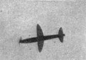
Almost like a real racer the Comet hurtles overhead. Note the tiny wing profile. THE COMET RACER By Don Orman The winner of the senior gas model event at the Junior Aviators National Meet designed and flew this racer 91. 4 m.p.h. at a club contest.
THIS model was designed and built for a club contest in Akron. Models of this design have been clocked at 91.4 miles per hour over a 120-foot course. A second model with slight modifications turned in a speed of 96 m.p.h. It averaged 80 m.p.h. for seven flights over the course. Construction is remarkably simple, and should register well with beginners for this reason. Yet the high speeds it attained make it worthwhile for the more experienced. Two types of construction have been used in the wing and tail surfaces, solid and built up. The model with the solid balsa construction turned in a slightly higher speed. While the plans have been prepared for the built-up wing and tail construction, either type is readily used. The necessary materials have been listed for both types. FUSELAGE The fuselage is built of 1/16" square hard balsa. First lay out the two side panels -- one over the other. Cut the bracing and cement in position. Note that the top and bottom outline of the fuselage is a straight line in the side view from about a third back. Auxiliary 1/16" square braces are cemented in the nose of the model, running alongside the longerons from the fourth cross-brace forward. The purpose of these inside braces is to strengthen the fuselage against the pull of the rubber and rough landings. 1/16" sheet balsa fillets are inserted flush with the outside edges of the longerons. These fillets are added to the front and rear of the fuselage and prevent damage to the fuselage while handling during the winding operation. LANDING GEAR The landing gear is bent from a single piece of wire 1/16" in diameter and 8" long. The actual length of each strut is 3". Cement and bend the landing gear to a piece of 1/8 x 1/8". Insert in the bottom of the fuselage, notching the ends of the balsa to fit alongside the longerons and inside braces. Cement the joints thoroughly and add balsa triangles of 1/16" flat for further strength. Wheels are cut to streamline shape from 1/8" flat pine. They are cemented to the wire axles to reduce vibration -- a helpful feature in getting maximum speed. NOSE AND TAIL PLUGS These are cut from balsa blocks to fit the ends of the fuselage. The rear plug is built of three thicknesses of balsa (indicated in the drawing and list of materials) cemented cross-grain. A rear hook of 1/16" diameter is inserted and the outside end bent in a loop to fit the hook on your winder. The end of the hook which holds the rubber should be bent so the fitting can be closed to guard against the possibility of the rubber strands slipping off. The hook should be firmly secured with a liberal coating of cement. 3/16" washers are used on both sides of the nose plug to reduce friction and keep the propeller shaft in perfect alignment -- a necessary feature for straight flight. An off-centered plug will cause additional drag and reduce speed. A ball-bearing washer between the propeller and the nose plug will provide smoother running with less friction loss. A clever substitute for this is to stick pins into the nose plug around the 3/16" flat washer. Let the heads of the pins fit over the edge of the washer. Not only does this anchor the washer securely, but it provides smoother running. The fuselage is covered with tissue. Tighten with water spray and follow with two coats of clear dope. WING AND TAIL SURFACES The wing may be built from 1/16" sheet balsa or built up as shown in the drawing. As pointed out earlier, the solid balsa wing and tail surfaces showed slightly higher speed. In using 1/16" sheet balsa, first lay out the plan shape of the wing. Sand to the shape of a wing section. The center portion of the wing which rests atop the fuselage is flat. Thus it is necessary to cut and cement the wing at two positions. 1/2" dihedral is added to each tip. The wing should be sanded perfectly smooth and given several coats of dope with intermediate sandings. In making a built-up wing use 1/32" sheet balsa ribs. The spars are 1/16" square and 3/64" square balsa. The trailing edge is a piece of 1/16 x 3/16". First build the center section and then build the two halves. When joining the three pieces of the wing, add balsa corners to strengthen the joint. Take special care to eliminate any warp or twist. Cover the wing with tissue and follow with water spray and two coats of clear dope. Tail surface construction follows that of the wing. If you used solid balsa construction in the wing, use 1/32" sheet balsa for the elevator and rudder. For built-up construction the method of constructing the elevator and rudder follows closely that of wing. The rib section is flat -- 1/16" square balsa. The outline of both rudder and elevator is sanded to a sharp edge. Cover and dope the tail surfaces. Notch the rudder to fit over the top of the elevator and cement both to the fuselage. Check their alignment with the thrust line. PROPELLER This is carved from a block of pine or brass wood. The full-size blank layout is included in the article. The blades should be cut to about 1/16" maximum thickness, tapering slightly toward the tips. Balance the propeller carefully. Sand out all the rough spots and apply about a dozen coats of dope. Then polish to a high luster with furniture or automobile polish. Bend a shaft from 1/16" diameter wire and insert through the nose plug. Add several washers (preferably ball-bearing) and insert the shaft through the propeller. Bend a hook in the end of the shaft and cement securely to the front hub of the propeller. FLYING Test flights are accomplished painlessly if you select a field with tall weeds or high grass to provide a cushion for rough landings. The approximate wing position is having the trailing edge between the eighth and ninth cross braces. Mount the wing flat atop the fuselage and secure with rubber bands. Measure out 12 strands of 3/16" flat brown rubber. The length of the motor should be an inch or two shorter than the distance between the shaft and the rear look. A shorter motor provides a more powerful burst of power and consequently higher speeds. Glides are no index to the adjustment of a speed model. It will be necessary to adjust your model under power. First put approximately fifty turns into the motor and point it up at about an angle of 85 degrees. That is, practically launch the model straight up. If the model dives instead of climbing, move the wing forward. The reverse procedure holds if your model looped immediately after launching. After several such trials you are ready to give the motor a full wind about 200 turns. If you are interested in maximum speed, release the model with a quick push. This will help it reach its greatest speed and fly a straight course. MATERIAL REQUIRED Fuselage
Wing
(Note: substitute a piece of balsa 1/16 x 2-1/2 x 9" if solid construction is preferred.) Elevator and Rudder
(Note: substitute a piece of balsa 1/32 x 2 x 8" if solid construction is preferred.) Additional Items
Scanned From August, 1938
|