|
Super Speed for Germany Detailed plans of an ultra-modern fighter in which appearance is emphasized -- the Heinkel pursuit. By Paul Plecan
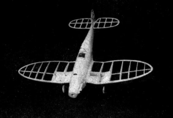
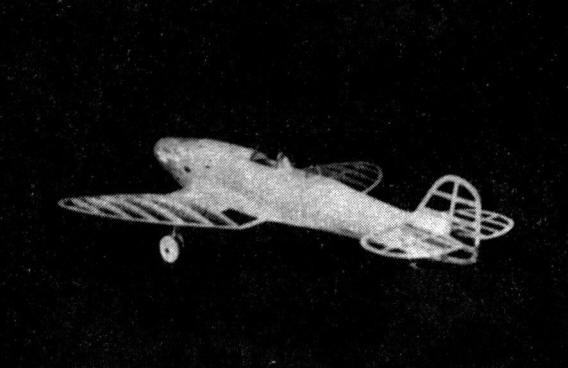
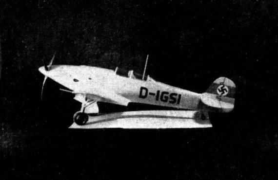
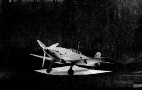
A MODEL of the Heinkel is one that is sure to be appreciated by any model builder. Its inverted gull wings and smooth fuselage give it a truly beautiful appearance. The original is powered with the "Jumo" of 685 horsepower, and is "armed to the teeth." There is a machine gun located on each side of the motor, a quick-firing gun in each wing, and there is a compartment in the under side of each wing stub for a total of six 22-pound bombs. The top speed of the HE-112 is 292 miles per hour, the cruising speed is 267 miles per hour, and the range is 680 miles with full military load. The model is a very fast flyer, and the enlarged stabilizer should be used if the model is built mainly for flying. When building the model, keep in mind the fact that a light tail is desirable, since the tail is so far back. Since the prototype is all-metal, we will make our model out of a solid balsa block, to retain the smooth appearance of the original. FUSELAGE Two blocks of the required size are selected for the fuselage. These blocks should be soft enough for easy hollowing, and should be identical as to weight. Cement the blocks together and trace the side view of the fuselage on one side. Cut to shape with a jig saw, and then trace the top view onto the top of the block, cutting to shape again. Using the templates for reference, carve the outside of the fuselage to the proper shape. Remember that the wing stub-fillet is carved into the fuselage, this method being easier than that of carving a separate fillet which is ordinarily cemented between the wing root and fuselage. After the carving has been completed, give the fuselage a coat of clear dope and sand down. A better finish can be obtained with the use of wood filler, however. Brush the wood filler on cross-grained, and follow with successively finer sandpaper. The fuselage may be split open at this point and hollowed out to the thickness shown on the plans. Due to the previously applied wood filler or dope, the outside of the fuselage will be found to be quite strong, so it may be hollowed out very thin behind the wing. Tools described by Mr. Booton in previous issues of Air Trails have been found to be the best for hollowing, so no mention will be made as to the type of tools needed. Before cementing the two halves of the fuselage together, cut the openings for the spar, leading, and trailing edges into the wing stub. The rear hook may be cemented in place at this time. A coat of wood-filler followed with sanding will hide the crack left between the two blocks after they have been cemented together. WING CONSTRUCTION The simplest way of making the wing is to make it in four parts, namely the two outer panels and the two center panels, which are cemented to the wing stub. To obtain the inverted "gull" appearance, do not forget to include a slight slant on the end ribs of each panel. Build the center portions of the wing first and attach to the wing stub. The leading edge of the wing is cut from sheet balsa, three pieces cemented together serving as a whole leading edge. It will be noted that the portion of the wing that the landing gear is connected to consists of two ribs cemented together, affording extreme strength, which is needed in a fast model such as this. The pieces "F," "G," and "H" also reinforce the wing, but are not necessary if the model is not built for flying. LANDING GEAR The landing gear is quite simple when started the right way. The bent wire piece "N" that is cemented to the two laminated ribs "1A" and "1C" absorbs the landing shocks, and the two small lengths of tubing let the landing gear swing outward and upward if a retracting landing gear is desired. Of course, a much simpler landing gear can be made out of plain wire struts if the model is for flying purposes and scale purposes are secondary. In a non-retracting type, the strut "K" is cemented in solidly, but in a retracting type it should be removable to allow the landing gear to swing upward into the wheel wells. The flap "L" completes the covering of the landing gear when retracted. The bottom of the wing is covered with 1/32" sheet for strength, and is utilized if the retractable type of landing gear is used. In the latter case, the wheel well is cut into the balsa, and when the landing gear has been swung into place, the bottom of the wing assumes a flat shape, unobstructed by any portion of the wheel or struts. TAIL SURFACES The tail surfaces can he constructed at this point, and a groove is cut in the rear of the fuselage to accommodate them. Proceed with caution when cutting the groove, since a slight difference in angles will cause the model to dive or stall. All the outlines and strips in the stabilizer and rudder are 1/16" thick, and the only precaution to take when making the tail is to avoid warping. The wing and tail surfaces are covered with tissue and evenly sprayed. While the tissue is drying, details may be added to the model. The exhaust stacks may be cut into the sides of the fuselage, and the small hole representing the shell ejector should be cut out directly behind it. The machine-gun trough is carefully carved in next, and then thin lines are scribed into the balsa with a sharp pencil to represent the different sheet metal motor covers. A small platform is cemented across the cockpit to support the headrest, and then small aluminum strips should be cemented in place to provide a foundation for the celluloid cockpit covering, which is applied next. The whole model is now given a coat of clear dope and sanded lightly. This is followed by two coats of gray dope. Wood filler waterproofs after the second coat, so the emery cloth or sandpaper being used can be moistened. The water is helpful while sanding because it keeps the wood filler from "filling up" the sandpaper. It has been found that Carorundum 320 wet or dry paper is best for rubbing away the excess wood filler. After this operation the model may be doped in the usual way. For finishing, always use a dope of good quality, and make sure that it is thin enough not to leave brush marks on the surface being painted. Black letters cut from tissue may be applied now, and the rudder insignia added. A red band is doped around the rudder, and while it is drying, a circle is cut from white paper. A swastika is drawn on it in India ink, and the circle applied to the center of the red band around the rudder. The author's model weighed one and three-quarter ounces, ready to fly, but this included a quarter of an ounce of clay in the nose, since the original model was tail-heavy. Six strands of 1/8" flat rubber were used, due mainly to the weight, which made the model very fast. A helpful hint to modelers who make a heavy model is to put a lot of undercamber in the propeller.
Scanned From June 1938
|
||||||