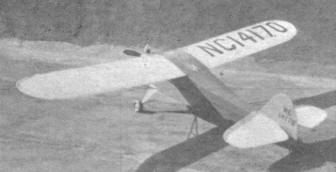
Taylor Young Gas Model A Cyclone-powered model of accurate design and By Paul PlecanIn collaboration with Gordon S. Light
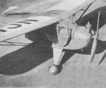
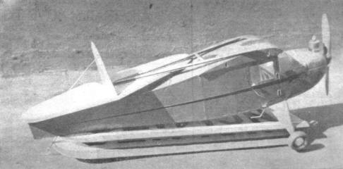
THE trim lines and pleasing flight characteristics of the full-size Taylorcraft do not suffer by a reduction in size. The 72" model is an attractive, top-notch performer. The scale is 1/6 full size and has been followed throughout with the exception of the elevator size and other minor changes necessary for successful flying. The NACA symmetrically shaped airfoil has been replaced by the Clark-Y, which has been found more suitable for models. An interesting feature of the model is the method of attaching the two halves of the wing to the fuselage. The ends of the wing spars fit into hollow spars or "wells" in the center section. Each half of the wing is supported by V struts. The wing is readily demountable. The door in the right side of the fuselage not only makes the model realistic but serves the useful purpose of providing access to the inside of the fuselage for attaching the wing and servicing the ignition system. CONSTRUCTION The fuselage assembly drawing has been fully dimensioned, and has been drawn to the scale indicated in the lower right-hand corner. Thus it is possible to find the size of any part of the model. When laying out the side panels of the fuselage remember that the door is on the right side of the fuselage. Consequently any upright or diagonal braces that interfere with the door are not included on the right-hand side-panel. The center section of the wing is built into the fuselage framework. The two center section ribs are cut from 1/4" flat. And early in the stages of construction check the angle of these center ribs. The flat undersurface of the rib should be parallel to the datum line. The motor is carried on two hardwood mounts (5/16 x 5/8") built into the front of the fuselage. The front of the fuselage directly back of the motor should be filled in with 1/4" sheet as a prevention against oil spray. The motor mounts should be spaced to fit the mounting flanges of the particular motor which you intend to use. The motor cowl is cut in two pieces. The portion above the datum line is removable. Both parts are cut from blocks and the inside gouged out to 1/4" wall thickness. Note that the bottom portion has a small hole at the rear-bottom as all outlet for the oil which is sprayed out of the engine exhaust port. Material for the cowling is conveniently obtained by cementing several pieces of balsa together to forth the block of necessary size. This is easier than trying to obtain a single block of balsa of this size. The door is four thicknesses of 1/16" sheet balsa laminated cross-grain and cut to correct shape. A door frame of 1/4" sq. balsa is built in the side of the fuselage. The door should fit snugly inside this frame. Aluminum tube-piano wire hinge are shown in the detail drawing. The "wells" in the center section must fit the ends of the spars tightly. And too, they must be set at the angle corresponding to the 3" dihedral which is put into each side of the wing. Use 3/16" sheet to build up the spar wells. Build them around balsa plugs corresponding to the size of the spars -- to insure a good fit. 1/8" diameter piano wire is used to form the main landing gear struts. Bend the landing gear in two U-shaped pieces which extend across the bottom of the fuselage. A 1/16" diameter piano wire spreader bar connects the two V-struts and prevents the landing gear from spreading outward in a "hot" landing. The tail skid is also 1/16" diameter wire. All landing gear and tail skid joints are bound with strong sewing thread and cemented thoroughly with sufficient time between cementings to allow for setting and drying. Sheet balsa (1/4") is filled in between the two 1/8" diameter struts which form the V on each side of the fuselage. Cut to a streamline shape and secure to the wire struts with silk or any type of fabric suitable for wrapping. WING The wing-Half shown in the drawing is for the right side. Be sure you remember the simple but necessary changes when building up the left wing-half. The ends of the wing spars extend about 3/4" beyond the last rib and are inserted into the "wells" built into the center section. 1/16" diameter piano wire hooks are cemented and bound to the ends of the spars. The two wing panels are secured in the center section by rubber bands connecting the hooks on the corresponding spars. These rubber bands can be readily put in place by reaching through the door-opening, and should be tight enough to hold the end-ribs firmly against the center section. Each wing panel is braced by a V strut made up of two pieces of 1/4 x 1/2" streamlined balsa. The attachment points for the struts have been indicated on the wing and the fuselage. Sheet metal lugs are attached to the ends of the V strut. Ordinary "tin can" metal will do nicely for these fittings. 3/32" diameter machine screws are used for attaching the struts both to the wing and to the fuselage. TAIL SURFACES Both elevator and rudder are flat. That is, no airfoil shape is used as the rib pattern. Spars and ribs are 1/4 x 1/4" balsa. Naturally the leading and trailing edges of both surfaces are cut away to a smooth sharp edge. The rudder is cemented to the top surface of the stabilizer and further strengthened with .035 diameter piano wire. Wire braces also run from the bottom surface of the elevator to the bottom-rear of the fuselage. These braces end about a half-inch from the fuselage, and hooks are bent in the ends of the wires. A rubber band connects these two wires, passing underneath the bottom of the fuselage and holding the wires under tension. This method provides an effective way of bracing the tail in addition to the help of keeping the stabilizer flat atop the fuselage. In addition the tail is secured to the fuselage by rubber bands passing over the top of the elevator and attaching to hooks mounted in the upright braces at the top-rear of the fuselage. ASSEMBLY The model proved to be a trifle nose-heavy, necessitating carrying the batteries under the trailing edge of the wing to obtain balance. As shown in the detail, the batteries are carried in a box which can be moved backward or forward between two 1/4 x 1/4" runners on the bottom of the fuselage. Wire hooks are spaced about every 1-1/2" along these runners, making it possible to secure the battery box at any position necessary to trim the ship. The elevator is set at neutral. The rudder is given a slight offset to the right. Be careful, not much offset is needed since the motor is set at one degree right-thrust. The wing is set at zero incidence -- its position being fixed by the center section -- and cannot be conveniently changed for any flight adjustments. But this isn't a handicap since the adjustable elevator and movable battery box allow ample leeway for trimming the model under all conditions. The model is covered with bamboo paper. As for color scheme and decoration, we suggest visiting your local airport, which is practically certain to have one or more of these favorite light planes. And if you're a demon for detail, the Deluxe version of the Taylorcraft will tickle you. It has wheel pants and a tail wheel -- plus other extras that will make interesting additions to your model. MATERIAL REQUIRED Fuselage
Wing
Tail Surfaces
Additional Material
Scanned From April, 1938
|
||||||||||||||||||||||||||||||||||||||||||||||||||||||||||||||||||||||||||||||||||||||||||||||||||||||||||