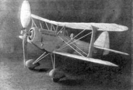
By Alan D. Booton Detailed plans for constructing another sensational flying scale model -- the Bleriot 510, combining detail with the ultimate in performance.
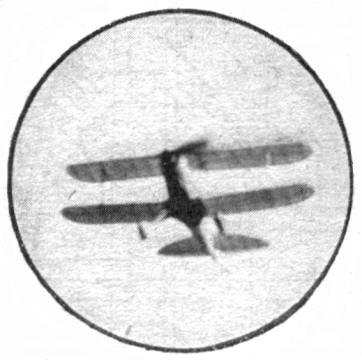
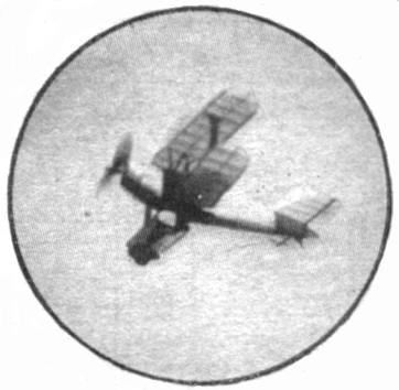
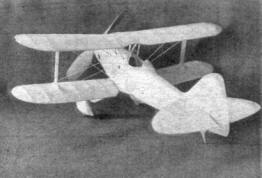
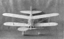
THOUGH the name Bleriot recalls daring flights made in flimsy planes at the beginning of the present century, the Bleriot 510 is one of the latest French single-seater fighters, nine times faster than the first Bleriot. The top speed of the 510 is 231 m.p.h. It is powered with a liquid-cooled Hispano-Suiza engine of 500 h.p. The model has the same snappy appearance and zest for flying. The construction is simpler than the usual flying-scale model. Being much lighter, it will turn in longer, more graceful flights without fear of damage. The shockproof landing gear is a great help. FUSELAGE Prepare a 4 x 6" sheet of 1/16" thick plywood and cut out the formers. Assemble one half of the fuselage frame composed of half formers from A to H, top and bottom longerons and the two stringers right on the drawing. When fully set, remove the half frame from the drawing and add like parts right on the first half. Now cement the formers B2 and C2 in place, then the 1/8" sq. landing gear and cabane struts support strips in the slots cut for them. Install the rear hook. Cement plain first bottom ribs to the ends of the fillet formers in the position shown and then cover the designated portion of the fuselage with 1/32" or thinner sheet balsa. (The fuselage may be completely covered with sheet if desired.) To shape a neat set of vents between formers A and B, slice through the sheet on the front lines and cement pieces in to flare the cover. Dope and polish the sheet cover with fine sandpaper, then carefully cement the bamboo fairing strips on. WINGS Assemble the wing frames right on the drawing, omitting the ailerons. Before removing the frames from the drawing, sever the ribs and insert the aileron parts. Crack the top wing members at the two second ribs and block the tips up 1/4 or 3/8". Then cement the cracked places and leave until dry, in order to maintain the proper dihedral angle. TAIL SURFACES Assemble the vertical and horizontal tail surfaces without shaping the ribs and spars. When the parts are dry, remove the frames from the drawing, trim and sand the ribs to the desired shapes. LANDING GEAR The landing gear is one of the simplest shockproof types. In preference to mounting the landing gear rigidly to shear off easily, a music-wire arrangement is used instead -- as shown by the detail on plate 2. The rear spring brackets only are cemented to the fuselage. The pants should be carved from soft blocks, doped and sanded, then hollowed out to allow the wheels to turn freely. Note that the diagonal wire braces also act as axles. NOSE AND PROPELLERS The scale propeller design is an oddly shaped metal type to turn clockwise. The flying propeller is of ample size to turn in excellent flights. Blank and carve it carefully, then dope and sand until glossy. Balance may be obtained by adding more dope to the light end. Note that the nose block is made in three pieces. The 1/8 " sheet is first cut out and the radiator grill effect pressed in, then the front portions are added. Cement the assembled block to former A and finish sanding to conform with the fuselage lines. The shape of the nose plug is clearly indicated, and should be a removable snug fit. Cement a 1/16" aluminum tube bearing in and then attach the propeller in the usual manner. A winding loop bent in the propeller shaft will be beneficial if a winder is to be used. COMPLETING THE MODEL Cement soft blocks to the lower wing fillets and sand them to conform with the first rib. Attach the top wing with a template block cut to conform with the space between the top of the fuselage and the center top wing rib. Cement the center struts firmly to the fuselage and wing ribs. Pin the lower wing ribs to the fillets and cut the "I" struts to between the wing frames properly. The horizontal tail frame main spar, must be notched at the center to let it rest at neutral incidence on former H. Check the vertical tail frame fit. The main idea is to see that all parts fit properly before covering. Cover the model completely with aluminum tissue, except the rudder, which is tricolored. Cover the curved wooden parts with small pieces. Now reassemble the parts with cement. Cover, color, and add all remaining detail such as tail skid, head rest, exhausts, vents, etc. The rigging wires are 1/32 x 3/64" bamboo. FLYING THE MODEL For normal horizontal flights, use two loops of 1/8" flat rubber with 2" of slack. For fast, high climbs use three loops of the first length. Test the model carefully until the proper flight characteristics are obtained. LIST OF MATERIALS
Scanned From February 1938
|
||||||||||||||||||||||||||||||||||||||||||||||||||||||||||||||||||||||||||||||||||||||||||||