|
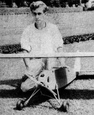
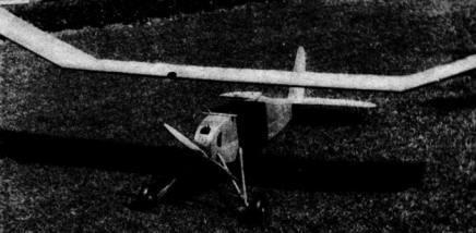
MAXWELL BASSETT'S WORLD'S RECORD GAS MODEL By Maxwell Bassett 19th Consecutive Air Trails Championship Model
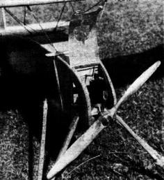
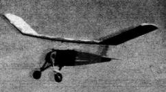
KEEP the model climbing steadily every second of the motor run" seems to be the keynote of Maxwell Bassett's contest success. His models are adjusted to make the most of the limited gas supply. Steep banks, stalls, and dives during the beginning of the flight merely waste fuel that should be used in gaining altitude. And regardless of how smooth the latter part of the flight may be, it can't equal that of Bassett's model which climbs steadily from the word "Go!" Of course, the soaring ability of his models converts the altitude into maximum duration. Miss Philadelphia VI was built early in 1935 and has flown in several contests. Last summer, when Maxwell made a last-minute decision to enter the National meet in Detroit, the model required only a few minor adjustments to put it in shape. The only real contest preparation he made was to build a spare wing. Despite being more than two years old, Miss Philadelphia VI took her place at the head of the gas model entry by turning in a record flight of 70:02 and winning the award for the most consistent flying. The model has a slow flying speed - not much faster than a fast walk. This can be traced to ample wing area and low weight. . The Cyclone motor provided ample reserve power for climbing, and the model got plenty of altitude before it started gliding. Bassett believes in ruggedness and simplicity of construction. Super-streamlining represents wasted energy and brings on complicated structures and gadgets that do not stand the wear and tear of consistent flying. Square-cornered fuselage, straight wings, and exposed landing gear struts do not handicap a model which flies at low speeds. The performance of his model throws considerable weight behind this argument. Low wing loading, a dependable motor, a steady climb, and a flat glide are important factors in deciding the outcome of a gas model contest. CONSTRUCTION Drawings used in this article have been scaled down from full-size plans. Because of space limitations, it is impossible to maintain any convenient scale. Therefore, each part has been dimensioned. The list of materials and the drawings call for spruce. However, any other available hardwood can be substituted. FUSELAGE CONSTRUCTION First make a full-size sketch of the side panel. Bend the longerons to the outline of the drawing by using 3/4" brads, nailed along the edges at 2 or 3" intervals. Cut the fuselage upright-braces and insert them between the center and the two outside longerons. Cement the rear braces first, and then progress toward the nose. Be sure that all joints are tight and provide a good cementing surface. Lift the two side panels off the drawing and join them together. No full-size top view of the fuselage is necessary. The widths at the various stations are available from the included drawing. After all cement joints are firm, round off the edges of the fuselage with a small plane and sand them smooth. Remove all rough spots that will mar the covering. MOTOR MOUNT Practically any of the popular make of motors can be installed with little trouble. The fuselage nose was originally designed to accommodate a Brown Jr., and the hardwood motor mounts have been spaced accordingly. However, the included sketch of the Cyclone Motor installation will clearly indicate the procedure to follow where the holes in the mounting flanges are spaced differently. Sheet-metal extensions are securely bolted to the crankcase shoulders and extend over to the motor mount where they are securely fastened, as shown in the sketch. Brass clips are used to help hold the batteries in position and to provide electrical contact. These clips are attached to the fuselage cross-braces with small wood screws. They should contact the battery firmly. Two 1/4" wide aluminum straps run over the tops of the batteries and fasten to the cross-braces. Rubber is bound across the bottom. All wires in the ignition system should be soldered. Make sure the joint to be soldered is thoroughly cleaned by sanding or scraping and the soldering iron is well tinned. LANDING GEAR Bassett has found this type of landing gear to be particularly rugged and serviceable. First streamline the spruce struts (lengths given in landing gear drawing). Be careful not to take too much wood off, thus weakening the struts. The rear struts can be tapered down to 3/8 x 1/4" at the end which joins the axle. The attachment fittings for the landing gear struts are made from #28 gage galvanized iron or steel. Brass of slightly thicker gage can be readily substituted. In attaching the fittings to the ends of the struts, first cement and bind them in place. After drying, drill the holes through the metal and the struts in a single operation. Insert a machine screw and nut as an additional guard against the fittings slipping off. The "V" strut and axles are made in one piece from 1/8" diameter piano wire. Another "V" strut is bent from 1/16" wire which extends down from the fuselage. The shock-absorbing effect is obtained by using rubber bands to bind the rear struts to the front struts and by using rubber to connect the two wire "V" struts. Use about fifteen strands of 3/16" rubber to join the struts and about five or six to connect the "V" struts. TAIL ASSEMBLY The tail group is an integral part of the model and is not removable. First cut the spruce elevator spars to the correct shape and length - tapering slightly toward the ends. The spars are then bound and cemented to the upright braces of the fuselage. At this point it is important to check the angle of the elevator, which should be 1 or 2 degrees negative. Bending the wood for the outline of the stabilizer is the most difficult step in its construction. A suggested method is to steam the wood for about an hour and then spring it into shape. Place brads around the outline of a full-size tail drawing to hold the wood in shape while it is drying. Successive steamings might be necessary to accomplish the sharp bends. Allow at least five hours for drying before the wood is attached to the spars. When joining the outline to the spars, make sure that the elevator is perfectly true. Bind each spar-outline joint with thread passed through a small 1/16" hole in the spar. Check the alignment again before adding the ribs, since it is practically impossible to warp the elevator after they are in place. Flat strips of hardwood (spruce) are used as ribs. These strips pass over the top and bottom of the spars and are bound to the outline. When drilling 1/16" holes in the ends of the ribs, clamp the end in a vise. This precaution prevents splitting the ends. Rudder construction differs from the elevator in that the ribs are flat balsa and it is made in two pieces. The forward portion (fin) is rigidly attached to the fuselage, while the movable portion is hinged by soft, copper wire hinges. An aluminum rudder adjustment is attached to the rear, lower edge of the rudder. Its shape is shown, full size, in the drawing. It clamps onto the rear edge of the elevator and is used for holding any desired rudder adjustment. WING Ribs are all practically the same except for slight differences in the notches for the spars, as indicated in the drawing. The first step is to join the center-section spar to the tip spars. Add the balsa gussets (H) and cement and bind the joint thoroughly. This operation is repeated with the leading and the trailing edges. Next add the ribs to the spar. After checking for alignment, add the leading and trailing edges. First complete the center section - keeping the wing flat on the workbench during the process. Then finish each tip - resting it flat on the bench until completed. Don't forget to insert the two spruce strips to the inside of the leading and trailing edges. These pieces support the wing saddle and must be cemented and bound securely. WING MOUNT Many of the successful characteristics of the model can be traced to the parasol design. Therefore, it is important that the wing be mounted above the fuselage in the position indicated. First make a full-size sketch of the wing saddle. It will be convenient to use in checking the shape of the wire. It is a rather difficult job to bend 1/8" piano wire, especially since the finished saddle must hold the wing in a very definite position - zero incidence. The interbracing - 1/16" wire - is soldered and bound to the main supports. Balsa farings are added to supply additional rigidity and streamlining. Flat strips of spruce are added to the bottom of the wire saddle where it rests on top of the fuselage. Small sheets of cork or rubber, glued to the bottom of these pieces, will cushion the bearing on the fuselage. COVERING All surfaces touched by the covering should be sanded smooth. When cutting the bamboo paper covering, allow about 1-1/4" overlap. The paper should be stretched tightly, using pins to hold it while the cement is drying. It will not be necessary to cement the paper to every rib or strut since the dope will penetrate the paper. Apply dope in a dry, warm room to prevent "blushing." Make sure there is no dust in the air - it will fall on the wet dope and roughen it. Use a soft brush and lightly stroke the dope over the paper. Colored dope can be applied after the first coat of clear. As many as three or four coats will be necessary to give a smooth, clear gloss. After each coat, rub the surface with 10-0 sandpaper. Take care not to sand through the paper-especially where it contacts the structure. FLYING First balance the model before attempting any flights. The center of gravity should fall about 3-1/2" back from the leading edge of the wing. The rudder should be set straight. The wing should be at zero incidence - that is, the flat undersurface of the wing should be parallel to the center fuselage longeron. The elevator should have about 1 or 2 degrees negative incidence. Now try a glide - launching the model from about six feet. Launch the model in a slight nose-down position. Watch the action in the glide. If it stalls, move the wing back a trifle. Be sure you maintain the zero angle in the wing. The curved, top portion of the fuselage will necessitate inserting blocks under the front or rear if it is moved from the original position. Carefully regulate the motor run to about 30 seconds. With the motor turning about half speed, head the model into the wind. Use as little power as possible for the trial flights. Since the model has such a slow flying speed, do not shove it violently as it is likely to result in a stall. Regulate turn by rudder adjustment. Warping the wing is unnecessary. The model seems to perform the best when turning in 200 - 300 foot circles. The weight of the model, ready to fly, is four pounds. Maxwell Bassett's championship model is manufactured in kit form by the Scientific Model Airplane Company of Newark, N. J. MATERIAL REQUIRED Fuselage
Landing Gear
Elevator and Rudder
Wing
Wing Mount
Motor Cowl and Installation
Additional Items
Scanned From February 1938
|
||||||||||||||||||||||||||||||||||||||||||||||||||||||||||||||||||||||||||||||||||||||||||||||||||||||||||||||||||||||||||||||||||||||||||||||||||||||||||||