|
Contest Gas Model A proven design that has been a consistent winner at many meets By Frank Ehling and Gordon S. Light
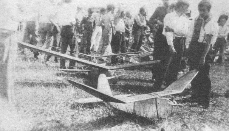
A GAS MODEL must be fundamentally sound in design and construction to withstand the wear and tear of flying. The fact that this model is recommended by Frank Ehling, its designer and builder, is proof that it fulfills this foremost requirement. His many years of experience with gas models has taught him what features to incorporate in a successful design. Other than simplicity and durability of construction, Ehling makes the following recommendations for gas models: The wheels of the model should be placed forward of the propeller, to prevent damage to the model in the event of bad landings resulting from poor adjustment or from hitting an obstacle and diving to the ground. A moderate-thick wing section should be used. It produces a slower flight under power and a better glide than excessively thin or thick airfoils. The ignition system should be carried in the bottom of the fuselage for a low center of gravity position and it should slide backward or forward on a track inside the bottom of the fuselage for easy balancing. The model should be finished with clear dope to give a transparent wing, with color dope used for the outline or scallops on the wing. This color combination will keep the model in sight the longest possible time. Modelers in general agree that these are necessary features for a successful gas model. This ship has all these features. And as you proceed with the construction you'll realize how thoroughly the design has been worked out. FUSELAGE The cross section of the fuselage is rectangular except at the nose, where the motor is faired into the fuselage. 1/4 x 1/4" hard balsa longerons and braces are used throughout the fuselage, unless otherwise noted on the drawings. The motor mount is cut from a piece of bass 3/8 x 3-1/4 x 14". This Motor mount is cemented to the inside of the upright members of the fuselage. It is reenforced with auxiliary cross braces and hardwood corner angles. The front of the fuselage is faired by cutting 4 curved pieces from 1/4" flat balsa and cementing them to the top and bottom of the longerons. 1/32" birch plywood covering is used to cover the bottom of the curved part of the nosing. The motor is cowled in with 2 pieces of aluminium cut to fit over the 1/4" formers. These aluminium pieces are cut to fit the motor and should allow for minor adjustments to the motor. For "servicing" the motor the cowl can be removed. An inspection door is made from 2-ply 1/16" sheet balsa. The location and size of this door is shown in the drawing. The door hinges are patches of adhesive tape and a small wire "catch" keeps it in position. At the rear of the fuselage, 2 additional longerons are built into each side of the fuselage. These longerons extend back to the rear tip of the fuselage, where they are joined to the bottom longerons with a small block cut from 3/8" sheet balsa. The 2 top fuselage longerons are cut off at the front of the elevator. The tail surface itself is carried flat atop the fuselage on the half longerons which have just been added. MOTOR INSTALLATION The complete ignition system is carried in a balance tray, which is placed in the bottom of the front of the fuselage. This balance tray is built up from 1/8" flat balsa as shown. Hooks are cemented to the sides of the tray and rubber bands fit over the top of the tray to hold the batteries, coil, etc., in position. The motor is mounted to the bass motor mount with small wood screws. The front of this bass motor mount is cut away to receive the motor and gas tank. PROPELLER A 16" medium-pitch propeller is shown in the drawing. It is cut from a block 1/2 x 1-1/2 x 16". Bass wood is the easiest wood to carve. But any other variety -- mahogany - cherry, etc. -- may be substituted. The block is first cut to shape, using the full-size template of the blade shape. Next it is tapered to 1/8" at the tips from 1/2" thickness at the hub. The propeller blades should be cut to an airfoil-shape cross section. Special attention should be given to careful balancing of the propeller and also to drilling the center hole. Mount the propeller on the motor, making sure that it tracks properly. That is, runs smoothly and does not wabble or vibrate. LANDING GEAR 1/8" diameter wire is used to form the 2 U-shaped pieces that make up the landing gear. The bottom of the U shape should be the same as the width of the fuselage. It is cemented and bound to the bottom of the fuselage at the indicated positions. The ends of the two U pieces are joined. Wrap the ends with soft copper wire and solder. A piece of .045 wire connects the 2 axles. It is also wrapped and soldered. Its purpose is to keep the 2 sides of the landing gear from spreading apart – the natural tendency after a rough landing. 3-1/2" diameter air wheels are slipped on the axles and kept in position with a drop of solder. WING The wing is built in three pieces. The center section is of uniform chord. The 2 tip - sections taper from 12 to 8 inches. A full-size wing rib is shown. It is cut from 1/16" hard balsa. Note that the rib shape allows for the addition of the sheet balsa covering of 1/16". This is added in 3-itch sections to the front and rear of the wing. At various points along the wing additional 1/16" covering is filled in between these 2 strips. Where the wing is not covered with sheet balsa, cap strips of 1/16 x 1/4" hard balsa are cemented to the top and bottom of the rib. When making the, tips of the wing it will be necessary to taper the ribs. This is most conveniently done by sketching a full-size drawing of the wing tip. The ribs taper from 12 to 8 inches at the tip. They also taper in thickness front 1-7/16" to 5/8" at the tip. The maximum depth of the ribs is located at about 1/3 the chord back from the leading edge. From the full-size drawing you've prepared, you'll be able to determine the required length and depth of each rib and cut them to shape. The sheet - balsa covering is added to each section of the wing before joining. When joining, follow the method illustrated. It will insure a solid joint between the center and tip sections of the wing. 1/16" birch plywood strips are cemented to each side of the spars and the joint is well bound with linen thread. After joining the sections of the wing, additional sections are covered with 1/16" sheet balsa as shown in the drawing. TAIL SURFACES A symmetrical rib shape is used in both elevator and rudder. A sample full-size rib is shown in the drawing. Cut all the other ribs to a similar shape. The main spar of the elevator is 1/8 x 1/2" and is the full depth of the rib. The ribs are cut in 2 pieces and these are cemented to the front and rear of the spar. A 1/4 x 1/4" leading edge is cemented to the front of the ribs and a 1/4 x 1/2" triangular – shaped trailing edge is cemented to the rear. 1/16 x 3/16" cap strips are cemented to the top and bottom of each rib. These cap strips extend over the spar and fit flush with the leading and trailing edges. The construction of the rudder is identical to that of the elevator. However, the leading and trailing edge is built up from 1/4 x 1" balsa. The pieces are cemented together and then cut to the carved shape. COVERING AND ASSEMBLY Bamboo paper is used as covering. It is good procedure to apply the paper to those parts of the wing and fuselage which have already been covered with sheet balsa. The paper will help strengthen the sheet - balsa covering. The top of the fuselage covered by the wing is not covered with paper. It will be convenient to make use of this opening when installing the ignition system. The wing is mounted flat on top the fuselage and secured with 1/8" flat rubber looped over the top of the wing and underneath the fuselage. The rudder is cemented to the top of the elevator, which, in turn, is cemented to the rear top of the fuselage. FLYING The complete model weighs 3-1/2 lbs. The wing area is about 7 sq. ft., making the ship rather lightly loaded. Test flying should be easier under these conditions. The model will suffer less from bad landings than a heavier model. Balance the model at the mid - point of the wing chord. The stabilizer has zero - incidence setting. The wing has one degree positive incidence. The original model was adjusted to fly against the torque (to the right with a right-hand propeller) and was adjusted to glide in the opposite direction. This was accomplished by offsetting the motor a slight amount to the right. The rudder was set at neutral and the left wing was "washed in" a slight amount. This allowed the model to turn in a smooth flight without any hair-raising banks and turns that accompany so many gas-model flights. Balance the model by means of the battery box in the bottom of the fuselage - sliding it backward or forward until the model trims at the mid - point of the cord. The balance tray is wedged in the bottom of the fuselage for the first few flights and later is secured with cement when the adjustment proves satisfactory. Gliding the model proves little about the balance unless you're experienced enough lo launch the model properly, and to interpret correctly, the maneuvers it performs in the short time required to glide to the ground. For all practical purposes it seems that trail flights under power are no more dangerous than trial glides. And they certainly prove much more. Observe a few precautions and your first flights will not be painful. Select a day when the weather is calm The model itself will require all occur attention without the additional worry of gusty air. The first flights should be made with a slight negative angle in the engine. This negative thrust will prevent the model from stalling. If the model is nose-heavy it will taxi harmlessly over the ground. But if it's tail-heavy the ending will probably not be as happy. Throughout the trial flights keep the motor running at reduced throttle setting. In the following flight, give the engine a trifle more throttle. And after that, the next step is to decrease the negative setting of the motor. Change the speed of the propeller and vary the angle of the motor until the most efficient flight is obtained with the flattest glide back to earth. Frank Ehling has offered to answer any questions that may arise concerning the building or flying of his model. So if there are any troublesome points, write to us. We'll ask Frank for the answers and send the information back to you.
Scanned from September, 1937 |

