|
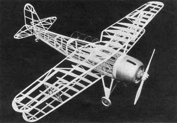
Building the Navy Type SBU-1 by PAUL W. LINDBERG Model Editor and Designer for POPULAR AVIATION
WE KNOW you will agree with us in building this Navy shipboard fighter, developed by our laboratory, that it is a very good lesson in the construction of Navy ships. The Vought SBU-1 is outstanding in appearance and an excellent flyer as well. A great amount of detail has been worked into the model, such as movable controls, shock absorbing landing gear and many other interesting features. COLOR SCHEME Fuselage - Gray and Silver. CONSTRUCTION OF FUSELAGE It is necessary to place a sheet of ordinary wax paper over the plan to prevent cement from sticking to the plan. In building the fuselage, construct one side at a time. The longerons, vertical and diagonal braces, etc., are held in place until securely cemented, by inserting straight pins on either side of strips. After the two fuselage sides are completed, they are pinned to top view of the plan, in such a manner, that the top longerons face down and the sides are at right angles with the table. The cross-members are now cemented in place, forming a rectangular fuselage. Cut formers from 1/32-inch sheet balsa and cement in their respective positions. See plan. Balsa nose plate is built up from 1/8 inch sheet balsa. CONSTRUCTION OF MOTOR Cylinders are carved and sanded from balsa blocks. Fourteen blocks required. To represent fins, wind heavy thread around finished block. Make crankcase as shown on plan. Rocker arm housings, push rolls and other small details of motor are made of balsa. CONSTRUCTION OF WINGS Cut all ribs front 1/16-inch balsa. Pin the spar in position on the plan. Now cement ribs in their proper locations. The leading and trailing edges are cut and sanded to shape and cemented to the ribs. The panels carry movable ailerons which are a great help controlling the flights. Make wing tips from 1/16-inch thick balsa. We highly approve of this type of wing tip, because it is much easier to construct and neater in appearance. CONSTRUCTION OF ELEVATOR AND RUDDER These are built from 1/16-inch square and flat balsa and all constructed on the plan. The construction is very simple, therefore, no difficulty should be encountered. CONSTRICTION OF LANDING GEAR After the struts have been carved and sanded, cement them to the balsa disk which cover the inner sides of wheels. The tops of struts carry bushings (cement securely) which receive wire shafts that are fastened to front nose plate and wing fillet. The shock absorbing wire between struts is fitted into curved piece of balsa under front part of fuselage. See plan. COVERING THE MODEL Apply tissue to the various frame-work members, using a light grade model airplane dope to fasten it to the outer edges. Stretch tissue as tightly as possible to remove all wrinkles. When edges have dried, apply coat of water to tissue. When all water has dried completely, tissue will become taut. May we suggest that you pin wings, elevator and such to flat surface. This prevents warping. ASSEMBLY After all parts have been covered, wing panels can be cemented into position. Take great care in fitting all wing struts. Small pins can be inserted into either end to simplify installation. The cockpit covering is made from wire and celluloid. Shape wire to correct form and cover carefully with celluloid. All other details and markings can be drawn with pen and ink. END Scanned From March, 1936
|
||||