|
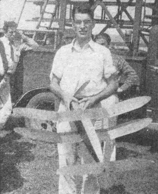
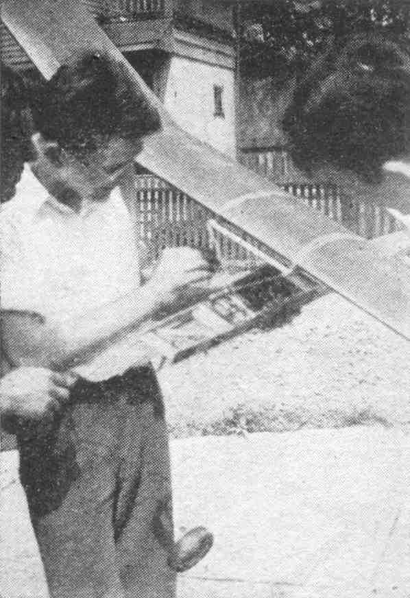
The DUPLEX Complete plans for building a championship model that holds two world's records -- fuselage and stick By Chester Lanzo in collaboration with Gordon S. Light
Chester LANZO'S models always turn in a good contest performance. But the Duplex is probably the most outstanding of all his contest designs. The Duplex holds 2 records. At a contest last year it was officially timed at 48 minutes and 45 seconds, one of the longest official flights ever turned in by a rubber-powered model. For the past year this model has held the National Aeronautic Association record for cabin fuselage models. Since Lanzo is over 21, leis record is catalogued as an Open Class Record to distinguished it from the Junior and Senior records turned in by modelers younger than 21 years. Lanzo proved his modeling superiority by converting this same model into a hand-launched stick model and flying it for another official record. It was a flight of 18 minutes and 10 seconds. The only change Lanzo made in his model was to substitute a slightly different fuselage. In the hand-launched stick-model event, no landing gear is required, as the models are hand-launched. And, too, there is no restriction on cross-section area. So the "stick" fuselage is slightly shorter and considerably "thinner" than the cabin fuselage. In all respects the 2 fuselages seem very much alike. The stick fuselage is built up and carries the motor internally, just the same as the cabin fuselage. This is a more convenient way of distributing the strain of the powerful motor than suspending it from a single stick, as was done in the old-type models. Both fuselages are built to fit the same nose and tail plugs. The wing is easily transferred from one to the other. The change from cabin-fuselage model to stick model is accomplished in a few seconds. Two-in-one is the best way to describe this model. By building one model, plus an additional fuselage, you'll have the benefit of two outstanding championship models. It's an inexpensive and convenient short cut in building up your quota of contest ships. Or, if you're a beginner, the Duplex should be an ideal way to acquaint yourself with the different types of contest models. The Duplex was designed to conform to last year's weight requirements of 1 ounce per 50 square inches. Therefore, it will be necessary to increase the weight about 2 ounces to bring it up to this year's weight rules. Lanzo suggests the following changes to meet the weight rule of 3 ounces per 100 square inches: a slight decrease in elevator area of approximately 5 percent; a decrease in propeller area and a decrease in diameter to 17 inches; larger nose and rear plug to facilitate winding with increased amount of rubber motor; a more substantial landing gear to take care of the increased weight of the model; closer rib spacing in the wing and tail, and closer spacing between fuselage uprights; and an increase in power to about 30-35 strands of 1/8" flat rubber. The details of these changes are left to your own judgment. The plans as shown here are for the original model as it was flown by Lanzo. CABIN FUSELAGE First we'll describe the construction of the cabin fuselage. It's more difficult to build than the stick fuselage. 5/64" sq. hard balsa longerons are used. If you're planning to increase the weight of the model, substitute 3/32" sq. hard balsa longerons. The sketch of the fuselage is fully dimensioned and you should have little trouble in making a full-size layout on a piece of drawing paper. First draw the thrust line of the model and dimension all parts of the fuselage with reference to this line, as has been done on the sketch. Both the rear tip of the fuselage and the nose block are demountable for access to the rubber motor. The nose block is cut from a balsa block 3/8 x 1-5/8 x 1-1/16". Metal plates are cemented to both front and rear of the nosing. The front plate serves as a bearing for the propeller and the rear plate is raised about 1/16" above the front plate to give the propeller 2 degrees of negative or downthrust. No right or left thrust is used. The nosing is secured to the front of the fuselage by a rubber band, which fits into a notch in the top of the nosing and extends down underneath the bottom of the fuselage. Wire hooks are cemented to the fuselage at the bottom of the second upright to receive the rubber bands. The rear tip of the fuselage (2-1/2" from the rear) is removable. Build the fuselage in one piece and cut away the rear tip after construction is completed. The rear hook is bent from 1/16" diameter wire and secured to the rear boom. When flying, the boom is attached to the fuselage with a few drops of cement applied immediately after winding has been completed. The tension of the rubber motor will hold the boom in place. By the time the motor has unwound the cement will have dried and will be capable of holding the boom in position. After the flight the boom call be removed by inserting a knife or razor blade. LANDING GEAR A single-strut landing gear is made from, bamboo. The corners of the bamboo struts are rounded with sandpaper and the strut is tapered from 1/16 x 3/16" to. 1/16 x 1/16" at the wheel end. The struts extend the full depth of the fuselage, the ends being joined to the cross brace at the front of the cabin window. This cross brace is strengthened by an auxiliary block of hard balsa 1/16 x 3/4 x 2-1/2" cemented flush to the top surface of the fuselage. The struts are also threaded and cemented to the bottom longerons. The wheels are 2 inches is diameter and are built up of 2 thicknesses of 1/8" balsa cemented cross grain. WING The wing is built in 3 sections. Each of these sections is completed --- built, covered and doped --- and then they are joined together to make the complete wing. The two tip sections are cemented to the ends of the center section, which is flat. Take care to make a snug joint between the tip and the center section. During the early stages of construction make certain the first rib of the tip section is staggered, so it will fit flush against the end rib of the center section to make a nice snug cement joint. It will be necessary to raise the tip section 5" (the necessary dihedral) when determining the correct angle for these ribs. Notice how the forward spars of the wing curve backward at the tips of the wing. This makes the wing tip easier to cover and prevents the tissue from sagging. There is no set procedure for bending the spars to this shape. Merely force them into position following the shape drawn in the sketch of the wing. ELEVATOR AND RUDDER In the construction of the tail surfaces, Lanzo should certainly prove to be a favorite designer for many modelers. He used a lift section in the elevator and this same rib shape for the rudder. This makes it possible to use the same airfoil template for both rudder and elevator ribs. Construction of the elevator and rudder is similar. The size of material is identical in both cases. The dimensions of the tail surfaces are available from the sketches. PROPELLER The large 18" propeller turned by an ample rubber motor is the secret of the model’s long duration and steep, fast climb. The propeller block is medium - grade balsa. The method of laying off the block is illustrated. The free -wheeler device is made from 1/16" sheet brass. The shape of the metal plates is shown full-size in the drawing. They are cemented and threaded to both faces of the propeller hub. 1/16" diameter wire is used for the propeller shaft. A loop is bent in the front of the shaft, after it has been inserted through the propeller. This loop fits onto the winder. ASSEMBLY The rudder is cemented atop the stabilizer at zero degrees. That is, the flat under-surface of the rudder should be lined up with the center rib of the elevator. The elevator is cemented flat to the top of the rear boom of the fuselage. The bottom of the rudder is cemented to the extreme rear tip of the boom. The wing is mounted flat atop the fuselage, using rubber bands for attachment. A 7/32" incidence block is inserted, as shown between the bottom of the wing and top of the fuselage. The original model weighed 4.1 ounces ready to fly. FLYING The power was 24 strands of Banko's Superlastic, 1/8" flat, gray rubber. The motor was 40" long and was soaked in lubricant for one day prior to the contest. It is wound by hooking the propeller shaft on the winder and stretching the motor out through the nosing of the model. The boom is removed from the fuselage and the other end of the motor is held at the rear hook fitting. The model flies against the torque in large circles. It should be adjusted to dip slightly when changing from powered to gliding flight. The durations turned in by the model show its ability to glide and take advantage of favorable currents. BUILDING THE STICK-MODEL FUSELAGE The stick-model fuselage is smaller than the cabin fuselage. The landing gear and the cabin are omitted. Special care should be taken when building this fuselage to make sure the front and rear ends will fit the nosing anal tail boom which you've already built for the cabin fuselage. Construction follows that of the cabin fuselage. The few differences are pointed out on the drawing. The nosing and the tail boom are mounted in the same way. Flying the model with the stick fuselage is practically the same as with the cabin fuselage. It will be necessary to move the wing back a trifle to compensate for the eliminated weight of the landing gear. The incidence of the wing is reduced to 1/8". Scanned from September, 1937
|