|
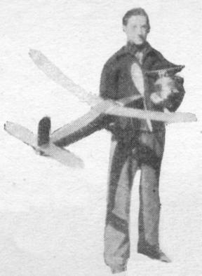
The STOUT TROPHY WINNER by Ervin Leshner and Gordon S. Light
THE STOUT TROPHY contest for fuselage models probably attracts more entrants than any other model contest. And since this contest is held only at National Contests, the best modelers in the nation compete yearly to determine who will have possession of the trophy for the coming year. Ervin Leshner was the winner in the contest held last July at Detroit. He had a nicely designed model and handled it like a veteran. The 36-minute winning flight was undoubtedly aided by a little good luck. But, in view of Ervin’s consistently good flying throughout the day of the contest, we can discount the luck element and attribute his victory to a triumph of modeling skill. But we're the ones who are lucky -- very lucky in having the plans for this outstanding model for this department. We feel they're a valuable addition to the list of championship models which have been presented in Air Trails. DESIGN The features Leshner tried to include in this design are those which every championship model must have: stability, simplicity of construction and flying, and a high power - to - weight ratio. And there is another feature which he put into his model, probably too obvious for him to mention but, nevertheless, important for winning contests it is the ability to turn in consistently good flights. Stability is the result of ample tail surfaces (34 persent) and comfortably long distance between the wind and tail surfaces. And, too, the 6" dihedral, which is added to each half the wing, is conducive to stable flights. Simplicity in construction is shown by the fuselage shape. It is square in section. Other than the cabin structure, there is no difference between the top and side views. The rudder, which is flat-sided, l, also makes for easy construction. The power - to - weight ratio was kept high by using a 22-strand motor and by reducing the structural weight. A minimum of wood is used. However, it is with out any decrease in strength. The method of building up the I-beam wing spar is evidence of maximum a strength with minimum weight. The model has all appearence of being a rugged out - door model which is built not only for long flights but also to be flown day after day long after its weaker brothers have been permanently grounded. The model can be made to conform to the weight rule, regardless of what changes are made. Its rugged construction permits an increase in rubber motor without any "beefing up." Leshner demonstrated the possibilities of this ship during last summer's flying. And it should make an ideal design to start off this summer's contest flying.
CONSTRUCTION The fuselage is of conventional construction -- even a trifle easier than the average, because of the square cross section. The main part of the fuselage is built and covered and then the cabin structure is added. 1/8" sq., hard balsa longerons are used. The upright and cross fuselage braces are 1/16 x 1/8" put in edgewise. At Several points along the fuselage, indicated in the drawing, the size is increased to 1/8 x 1/8" balsa. Both the nose and rear ends of the fuselage, up to the frist cross brace, are covered with 1/16" sheet balsa. Since no motor stick is used, the fuselage must stand considerable rough handling, which is concentrated at these two harts of the fuselage. Sheet - balsa covering makes the fuselage more durable. The fuselage should be fitted with nose and tail plugs, The rear plug is made from two pieces of 5/32" balsa cemented cross-grain. The front plug is cut from two pieces of balsa. The semicircular nosing is cut from 5/8 x 1-1/4 x 1-1/4" balsa and cemented to a piece of 3/16" flat balsa, which is cut to fit snugly inside the front of the fuselage. Notice the notch which is cut in the nose plug, and the rubber - band attachment which is used to hold this plug in place. 1/4" washers are cemented to both the inside and outside of the front plug. These washers should be cemented so the shaft is staggered at a 2-degree negative angle. A small ball-bearing washer is used between the nose plug and the propeller. A good bearing surface is necessary with large robber motors. LANDING GEAR Single struts Of bamboo 1/8 x 1/4 x 9" cut to a streamline shape are used for the landing gear. The wheels are extended about 3" beyond the ends of the bamboo strut. They are carried on axles of .035 wire bent to the shape shown in the drawing. The purpose of this peculiar bend is to prevent the wheel from turning in or out when landing. Landing - gear sockets are made by wrapping several thicknesses of cement - coated writing (or any other stiff paper) around the end of the strut and binding with thread plus a liberal coating of cement. The landing - gear strut is removed while the cement is still dry. And when the socket has dried, it is cemented in place inside the fuselage. Both landing - gear sockets are made at the same time. The position inside the fuselage is evident from the drawing. Notice the diagonal strengthener of 1/16 x 1/8" balsa, which is added to the fuselage at the point of landing - gear attachment. COVERING THE FUSELAGE The fuselage is covered with tissue, as the next step its construction. And after doping the tissue, the cabin is added. Notice that the sheet balsa at the ends of the fuselage are covered with tissue. ADDING THE CABIN STRUCTURE The cabin is intended as a place for mounting the wing, with a view toward good streamlinig, and, also, to inclose the center section of rite wing inside the fuselage and avoid having the center section counted as effective lifting area. The top of this cabin structure is hinged about the rear and is held in place with wire hooks and eyes at the front edge. 1/8 x 1/8" hard balsa is used throughout the cabin structure. When joining to the fuselage, take care to scrape away the tissue at the cementing surface and make certain to cement the wood directly to the longeron. A tissue-paper hinge is used at the rear of the movable top portion. The entire front portion of the cabin is covered with cellophane. WING The Eiffel 400 airfoil is used in the wing. It is a popular section among modelers. Leshner selected it because it is a high-lift section with its highest lift to drag ratio (22) at minus .75 degrees. This airfoil is excellent for the glide. And since most of the duration of a model's life is spent gliding, the Eiffel seems to be an excellent selection. The type of spar construction which Leshner used is strong and lightweight. It is a trifle more tedious to build up than the conventional type. but it seems to be worthwhile investment to work out the details. The main spar of the wing is 1/32 x 1/2". But to reenforce the spar against bending, strips are added to the top and bottom. The spar is practcally the same depth as the rib. Therefore, it is necessary to cut a notch in both the rib and the spar, forming a "lap joint" The spar is notched to a depth of 1/4". The rib is notched just slightly deeper. The final joint should be made so that there is a 1/32" space remaining between the top of the spar and the top of the rib. A piece of balsa 1/32 x 1/8" balsa is fitted into this notch. It is cemented to the rib and to the spar. A similar strip is added to the bottom of the spar. The finished spar should resemble an I-beam. A section through this I-beam is shown. An auxiliary spar is added to the rear of the rib. It is 1/16" square, hard balsa. It fits into the bottom of the rib. A leading and trailing edge are cemented in place to the ends of the rib. The trailing edge is notched 1/16" to fit the rear edge of the rib. Be careful to cement the trailing edge to the ribs so it is turned slightly down – ward. It should round out the top and bottom camber of the airfoil section. The wing is made in two pieces. The tips are bamboo, 1/16", rounded. The balsa tip strengtheners are shown in the drawing. The two halves of the wing are joined by a center section which consists of 3" lengths of spar, leading and trailing edges. No extra ribs are needed when joining the two wing halves. 6" dihedral is given to each half the wing. The center section is covered on top with 1/32" sheet balsa. ELEVATOR This construction follows the same general method as the wing. The Clark-Y airfoil section is used. The type of spar is simplified. It is merely a piece of 1/16 x 1/4" balsa fitted into notches which are cut in the ribs. The trailing edge of the elevator is notched 1/16" to receive the ribs. Bamboo tips of 1/16 x 1/16" are added to the elevator. The center section of the elevator is covered with 1/32" sheet balsa. RUDDER The rudder is shown exact size in the drawing. The rudder is fixed rigidly to the top of the elevator. Rudder control is obtained by a small, movable balsa tab which is attached to the rear. It is cut from 1/32" sheet balsa and soft iron-wire hinges join it to the main part of the rudder. The rudder is flat -- no ribs being used in the construction. The elevator and rudder are attached by two wire clips. The rear clip is cemented to the bottom of the trailing edge and the front one to the leading edge. The exact size of these attaching clips are indicated. Their size has been fixed to give the elevator two degrees of negative incidence. If your fuselage has been accurately built you can check this incidence directly from the drawing. PROPELLER The 18-inch propeller, with its ample blade area, is a major item in the ship's performance. Any extra care given to the carving of the propeller will pay high dividends in better flights. The propeller block is shaped as indicated in the drawing. 1/4" camber is put into the rear face of the blades. The blades are cut to correct thickness and correct camber before rounding the ends. The fullsize blade shape should be used to get the correct propeller shape. The template should be placed on the blade so that the leading edge of the propeller at the center is straight. That is, the front of the hub of the propeller should not be cut away. All excess wood should be cut away from the rear of the hub. The propeller is highly polished so it will glint in the sun. Polish it with a fine grade of sandpaper and apply 4 coats of liquid wood polish. This polish can be made from 1 part banana oil, I part cement, and 1/20 part castor oil. The castor oil is added to prevent the wood from becoming brittle. After the last coat is dry to the touch, rub vigorously with a soft cloth. And at this point Leshner very amusingly added that, despite his forethought in making a shiny propeller, it never had a chance to glitter in the sunlight. The sun ducked behind a cloud and never once showed itself during his 36-rninute winning flight. FLYING The model was adjusted to turn against the torque. The ship took off at a low angle of attack and gained altitude in about 200-foot circles. The glide was a tight circle about 30-foot diameter. The sinking speed was remarkably low - a characteristic which substantiated Lesher's choice of airfoils. The motor was wound outside the fuselage and then pulled through with a winding hook and attached to the propeller shaft and the rear hook. On the winning flight 550 turns were stored in the motor. And this is by no means the maximum number of turns. The power of the 22 strands of 1/8" brown rubber was so great that Ervin wasn't able to pack in any more turns with the small winder that he happened to be using at the time. On previous test flights, with 300 turns hand-wound in the motor, the model made 5 consecutive flights of exactly 3 minutes. The flights were made in still air about 7 p.m. On these flights the propeller turned about 1 minute and 5 seconds. FOR A CHANGE IN WEIGHT RULES We've asked Ervin to tell us what changes he'd make in the model to adapt it to the new weight rules which more than likely will govern this summer's flying. He based these suggested changes on the assumption that the weight rule will be changed to 3 ounces per 100 square inches. That means a 50-per-cent increase in weight for the same area. Thus, with this ship of 208 square inches, the minimum weight would be raised from 4.16 ounces to 6.24 ounces. Since this model weighs 4.27 ounces, the increase would be slightly less than 2 ounces. This could be taken up with an increased length of motor, using a slack-rubber device to prevent the extra rubber from shifting back and forth in the fuselage and unbalancing the model in the glide. To make better use of this increase in power a slightly larger propeller could be used. The fuselage of the model is strong enough to take the extra power and no changes in the structure would be necessary, other than a slightly larger rudder. Leshner has noted a slight tendency of the model to spin because of the weight of the rubber in the rear of the fuselage. This condition might become serious with a heavier motor. So to avoid this entirely, Leshner suggested that part of the 2-ounce increase in weight be used to increase the area of the rudder about 5 square inches.
Scanned From May 1937
|
|||||||||||||||||||||