|
How to Build the Wakefield Mayfly II The Story of How One of the Finest of Contest Models Was
Developed by an By C. S. RUSHBROOKE
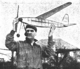
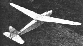
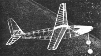
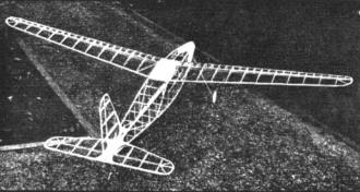
IN PRESENTING this model to the great American public of aero-modellers, I do so in a spirit of trepidation that my views may be taken as being representative of general English practice -- with the possible result that I will be "hounded" by the large number of British enthusiasts whose ideas differ from mine. However, I am consoled with the knowledge that the machine here described has at any rate justified the time and thought given it, subsequent experiences and successes having been very gratifying to myself. Whilst durations have been quite up to scratch, the general handling, strength and stability features that became apparent under severe tests were such that much satisfaction was felt, considering the fact that the machine was designed purely for duration purposes. Actually this machine is a development of the job sent to St. Louis last year for the Moffett Trophy contest, gaining 8th place. Much was learned from the first model, and subsequent modifications are the result of experiences gained with this machine -- the "Mayfly I". The original wing section of "Modified Clark Y"' has been substituted with "R.A.F 32", this section being found to give better soaring, and a much slower flying speed. Also the wing area has been increased from 198 to 206 sq. in. This was done to take full advantage of the greater area allowed in the Wakefield rules -- the second machine being built for this contest. In setting out to design this machine, various factors and previous experiences were taken into consideration; the main point kept in mind being the sad experience in the 1931 Wakefield contest at Warwick. It is past history that the competition was held under vile weather conditions -- and my model built for that year being of fairly light and "fair-weather" construction, went all to "pot" owing to the thorough soaking it received. Being a single motor job, the fuselage twisted under the rubber torque, with a consequent upsetting of flying trim. Bearing this experience in mind, I decided to build the present machine with a degree of sturdiness and inherent stability to take care of adverse weather conditions, even at the sacrifice of a certain amount of the ultimate duration. The model on test showed all the points aimed for to a marked degree, and the durations obtained in subsequent contests etc., have been extremely satisfactory. Average duration is around the two minute mark under fair conditions, and the ability to soar has been proved on numerous occasions -- the best flight to date being just over five minutes. The most pleasing feature to me has been its ability to buck the elements in no uncertain manner, and under English conditions -- where on the arrival of a really fine flying day one is almost too staggered to take advantage of it -- this attribute has enabled it to more than hold its own, as the records gained go to show. Successes have been numerous in our local contests and on two recent occasions where visits have been paid to neighboring clubs, I have managed to bag the chief duration contests held. I hope to enter this machine in various National competitions during the coming season, and feel confident that I shall at least not disgrace myself ! ! The construction details will perhaps strike the majority of American builders as on the hefty side, but I would make it clear at the outset that for one thing, I wished to obviate any recurrence of the warping tendency, and to produce a model that would stand a prolonged session of hard flying, being unable to devote the time I should like to bringing out more than a very few models a year. Extensive use is made of sectional materials and the strength gained by this practise is something to be experienced to realize -- in fact the uncovered fuselage was strong enough to take the torque of the rubber motor without any appreciable amount of "give." Should anyone thick I erred, in making the skeleton work too strong in this direction, I should note here that it was intended to make experiments with twin motors and gears, hence the ruggedness used to take care of compression strains. The propeller used will be strange to American eyes, and I will most likely be accused of using too fine a pitch and too scanty blade area. Whilst not perhaps being the most efficient type for American use, one must not lose sight of the vastly different conditions under which we fly. I have found that a medium type prop is the most suitable for our general use, the fairly fast revs. giving the machine a good climb to the upper regions where the thermals are the more likely to be found. By using a box arrangement for the main spar, I introduced an arrangement that I have conclusively proved to be the strongest method coupled with lightness that it is possible to find. It is not difficult to make and in tests was proved to be three times as strong as a corresponding spar made from the solid, with a saving of over 50% in weight. Coupled with a fair sized leading and trailing edge, this wing has stood all kinds of hard wear -- the only occasion when repairs were necessary being the time it wrapped itself around the radio control tower at our local airport. One factor that might present itself is the ease of transportability gained by the fact that everything is detachable, with a consequent small packing space. This is a point that has struck me in the majority of American designs -- especially flying scale types -- it being almost necessary to have a truck to convey the models to a contest!! It will be noticed that use has been made of balsa veneer as a strengthening material at various points. This I have found more than compensates for the slight extra weight involved, and I am now experimenting with the use of fillets, etc., it being my opinion that the improved streamlining obtained will more than outweigh the disadvantage of additional weight. I have come to the conclusion that streamlining is of paramount importance in the advance of model design, just as it is in full size practise, and I think the most conclusive proof of this is the experiments made by Frank Zaic, and reported by him in his recently published "Model Aeronautics Year Book." Before getting down to detail description, may I clear myself by saying that this is not exactly a super-duration model, though the ability to shine in this direction is there. Strength, ease of handling, and a consistent average duration of proportions to enable it to hold its own are the main features, and one must not lose sight of the fact that this machine was designed specifically for English conditions. Modifications to suit American conditions may be advisable, and I should be pleased to hear from anyone who tackles this job as to any alterations made -- if any -- and their experiences in both building and flying this "brain-child" of mine. And now to the real job of construction: Fuselage This is constructed from medium hard balsa, the longerons being of 3/16" x 1/8" L section, with uprights etc. of 1/16" x 1/8" and 3/16" x I/8" T section. This latter section is used at the main stress points such as the under-carriage bay, and the points where the wing holding bands pass round the fuselage. Corner braces are inserted at these points with a view to taking the twisting strains that take place under full turns. Cross-bracings are all inserted on the inner faces of the fuselage sides. When steam-bending the longerons, I have found it best to hold them in pairs, back to back as shown in sketch, this method obviating the tendency to kink. When building the sides, I pin the longerons to a board with very fine pins. After one side is completed, this is taken up and reversed, the second side being built directly on top of the first. We thus have the two sides together with the outer faces meeting. Before separating, it is easiest to sand the outer edges all around, thereby insuring that both sides are equal. The sides are now split apart with a razor blade, and the outer faces smoothed. After the cross pieces are inserted, the fairing on the nose is formed with 1/16" square stringers and 1/32" sheet balsa. This forms a really strong section, able to stand a great deal of knocking about, and at the same time something one can really grab whilst the motor is being wound. The rear motor fixing consists of a bamboo peg, this method being very easy to handle. Tail skid is also of bamboo, of easy and simple design as will be seen from the drawing. Undercarriage Formed of bamboo, wire and 2" balsa stream-lined wheels, this portion is simple yet with ample strength to take care of all normal landing shocks. When not in use the legs are disconnected by removing the rear pins from the brass tubes, whereon the whole folds flat along the fuselage, making for a saving in packing space. Nose Piece This is made from 3 ply hard balsa, with a brass bush to take a prop shaft of 16 gauge piano wire. (It should be noted that all wire sizes quoted are of English gauge). The method of free-wheeling is seen best in the illustration, while the method of prop retention makes for an easy and quick change should same be required. The size of wire used for the shaft could be reduced, but I use this gauge as standard on all my machines, with the advantage of being able to use any prop I may have on any machine. This will be found of advantage in experimenting -- and saves one being stuck should the prop to any particular machine be broken. Propeller Cut from a block of hard balsa, 16" x 1-1/4" x 1-1/4" the original was left rather on the stout side. The method used by Frank Zaic, e. g. carving the blades thin and covering with Jap silk would I think be a distinct improvement. Leave the hub strong, as the winding is done by the prop. Alternately, an S hook could be used engaging with the prop-shaft. Wing This, perhaps the most important part of any model, is of fairly easy and straight forward construction. The section used, R.A.F. 32, enables a good depth of spar to be used, and by utilizing the box-spar arrangement before mentioned, a degree of sturdiness is obtainable that will take care of a good deal of knocking about. The main spar is made by cutting four side plates from 1/32" stock, and assembling into box form with the aid of 1/16" square balsa strips as shown. Ribs are of 1/32" stock, with the exception of the four center-section ribs and the first two ribs out from the center, which are of 1/16" hard balsa. A good, solid leading and trailing edge to the dimensions shown, with sheet balsa tips make for a strong job. The ribs are slotted onto the spar as shown, this method preventing the covering from sticking to the spar and spoiling the section. Riblets are used to prevent sagging and contribute their quota of strength to the whole. Note that all ribs and riblets are cut out for lightness fore of the leading edge. The center section entails a bit of extra work and can be omitted if the builder doesn't mind carrying a "coffin" around with him, the only reason for the halving of the wing being for ease of transportation. Two 1/8" dowels are used, fixed to one half, and sliding into tubes located in the opposite half. The tubes are made from 1/32" sheet wrapped around a piece of the doweling used. The drawings should make this part clear. Four small bamboo pegs are cemented into the center section to take the rubber fixing bands. A dihedral is built in to the extent of 3-1/2" at the tips. Tail Plane Of straightforward construction, this consists of 1/32" ribs of a neutral section, 1/8" x 3/16" leading edge, 1/4" x 1/16" trailing edge, and a tapered spar cut from 3/32" stock. Ribs are slotted onto the spar as in the wing. The spar and trailing edge are carried through in one piece, and the required incidence is obtained by the depth of the wire saddle. Note the spar goes into the slot cut in the fuselage stern post, and is locked in position by the fin. Balsa veneer is used as shown, this preventing the pulling inwards of the end ribs, with a consequent slackening of the fit to fuselage. Fin This consists of 1/32" ribs slotted onto a T section spar, with leading edge of 1/8" square, and trailing edge of 1/4" x 1/16". The T spar gives a good, stiff structure, and the fixing to the fuselage by the two bamboo pegs shown saves any wobbling. Adjustment is made by the double-wire saddle, the bottom rib being a sliding fit in this. It should be noticed that the interlocking method employed enables the complete tail assembly to be fixed by one rubber band. Covering, Etc. The whole machine is covered with superfine Jap tissue, water doped, and given one coat of clear model dope. On the original, I waterproofed the whole machine (after the decoration and coloring had been applied) by the use of a clear cellulose varnish thinned down with dope thinners. This latter operation is rather necessary in our clamp climate if one wants "all the year round" flying. Power Ten strands of 3/16" black rubber are used, with an original length of 2" slack above the mean length between hooks. This of course stretches with use. Maximum turns are about 850 with safety, stretching the motor 2-1/2 times. In conclusion, I should like to acknowledge the great help received from Mr. J. W. Kenworthy during my short period of model aeronautical activities, without which I should still be struggling along with the greenest novices. The fuselage construction used in the "Mayfly" is a development of his successful "Conqueror" model, that won the Wakefield Trophy in 1933. And now -- those interested enough. Let to it, -- and don't forget to let me know how you get on. I should be glad of any data such as performance, etc., to enable me to check up on my figures -- always with a view to bringing out something better. Scanned From September 1936 |


