|
The FOKKER G - 1 A Double Fuselage Flying Scale Model by Alan D. Booton
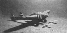
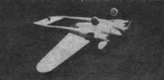
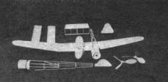
SINCE the data on this ship has been given on other pages of this issue, let us start the model. Read the directions and study the drawings carefully. You will note that the model is a 1/64" sheet-covered, all-balsa type and that the main frames are of the simple, rectangular type with the formers added. Provision has been made to get better performance from the model by the use of extension nosings that permit the use of longer propellers, if desired. The tail surfaces are removable for rubber installation, and change from flying to scale surfaces. WING Where wider sheets of the 1/64" sheet are required, butt cement the 2" sheets together to the appropriate width. From such widths cut four oversize wing-panel patterns and two center section-panel patterns 1/8" oversize in chord. After the ribs have been cut out, make a pair of slotted main spars for the wings tapered to the last rib and wide as the wing is thick, also one center-section spar. The slotted main spars make possible the assembly of the wing panel parts without additional drawing. The assembling should be done on a soft, smooth board. Taking one panel as an example, lay one of the wing-panel patterns on the board and assemble all the parts on it, using the trailing edge as a guide line. Slant Rib 1 for dihedral. Use plenty of pins to hold the parts in place and then cement all joints. When dry, "toenail" pins on a slant through the outside of Rib 1 and at the tip, then remove all of the other pins. Flow cement across the tops of all ribs but the tip, and on the trailing edge and leading edge. Do the cementing quickly. Starting at the trailing edge, lay the top cover on. Pushing in pins where needed, smooth over to the leading edge, using still more pins. Make the two other panels and cement them together with 1" or more dihedral angle at the tips. Cement the tip edges together. Several of the scrap balsa clamps as shown on Drawing 3 will hold the edges together. Cut out the ailerons by holding the wing to the light and cutting between the spars. Reattach them with soft wire hinges. CABIN AND BIFUSELAGES Make 2 cabin side frames and 4 bifuselage side frames from the side views, then space them apart according to the top views, using 1/16" sq. throughout. To these frames, cement the formers in their proper positions, i.e.: C1T goes on top of the 1st cabin station, C1S goes on each side of the 1st cabin station, and C1B goes on the bottom of the 1st cabin station, etc. When the B3 stations on the bifuselage are reached, they are continued by the longeron former method. The rounded nose of the cabin and the forms behind the cowls are carved and hollowed as indicated. The cowls are made simply by wrapping the covers (1/32" sheet) over the prepared disks. Rubber bands hold the covers until the cement dries. Conventional nose plugs are used. Leave the carved parts and cowl off until the model has been covered. RUDDERS AND STABILIZER Taking one rudder for example, it is 1/64" sheet-covered and has no frame. The 1/16" streamline ribs are cemented to the 1/16" leading edge and left to dry. Cut 4 rudder patterns to cover above the bottom rib. Cement the edges of the ribs and around the edge of one pattern and cover the ribs as making a sandwich. Fasten the edges of the sheet together with the scrap balsa clamps mentioned above. Cement formers 6 and 7 in place on the lower rib. Former 6 must have the rear hook and end plug mounted. Cover the remainder of the rudder longitudinally. The stabilizer frame is made on a completed drawing and cemented to the rudders according to the position on the side-view drawing of the rudder. Leave the stabilizer covering until later. REMAINDER OF COVERING Slip the cabin frame to the center of the wing and pin in place, then cement all points of contact securely. Slip the bifuselage frames on the wing and plug in the tail assembly. The center lines of the bifuselage frames, when parallel should match the position of the top-view drawing, but 1/16" variation will not differ. Pin the bifuselage frames so the stabilizer sights in line with the center section and then. cement all points of contact. Cut away portions of the cover and spars to allow motor clearance under the wing. Cover stabilizer with 1/64" sheet. Cover the bifuselages first. One, as example: cover top, then bottom between B1 and B3; top, then bottom between B3 and B4, and all around between B4 and B5. Make paper patterns of each section before cutting 1/64 " sheet. The patterns can then be used on the other frame. The cabin is simple to cover to the bottom of the wing, but make paper (full length) patterns first. The bottom should be covered with full-length "barrel stave" shaped strips of 1/32 " sheet, about 3/8" wide, starting at the center of the bottom. Cement the landing gear in place. Cement the cowls and forms to the bifuselage and the nosing to the cabin. COLORING AND DETAIL Spray the whole model with clear lacquer thinned to 1/2 and 1/2. Let it dry and then sand all over with fine paper. Mark the spaces for the insignia colors and mask over them with masking tape or in a similar manner. Cement on all detail except cannons and celluloid parts. If cut-out observer's windows are preferred, cut them now. The whole model is now sprayed with a hand spray (or professional gun, if available). The color is "U. S. blue," thinned half the original consistency, and must be lacquer, instead of dope. Dopes will ruin the sheet covering. One light coat sprayed on should suffice, whereas, by brushing, two heavy coats might show streaks. Remove the masking and brush on the "imaginary insignia" of red and white bands, where indicated. Now cement the celluloid parts on, the tail wheel, aluminium tube guns. Paint tires and motor fronts black. PROPELLERS Note on Drawing 1 the provision made to increase the endurance of the flying model, by adding special nosings to the motor fronts, so 5/8" longer props can be used. Make 6 propeller blanks; cement 3 together to make the two three-blade blanks. Carve one left-handed propeller and one right. When cementing the propeller shafts on, bend winding loops on the front. FLYING THE MODEL The original model weighs 2 oz., ready to fly, with each propeller powered by 6 strands of 1/8" flat lubricated rubber. After installing the rubber, lightly cement the tail assembly to the bifuselage ends. The model must balance along the main spar. Make the first glide and power tests in a field of tall grass. If tall grass is not available, make the tests r.o.g., gradually increasing the number of motor turns until perfect adjustments have been made.
Scanned From April 1937 |
||||||||||||||||||||||||||||||||||||||||||||||||||


