A Flying Douglas Attack Bomber If You Want A Fine Flying Modern Low-Wing Warplane Model -- Here It Is By SIDNEY STRUHL
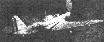
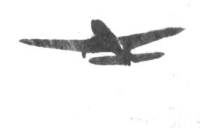
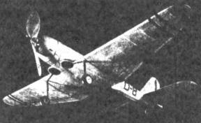
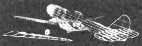
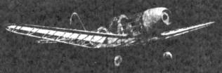
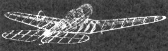
Our flying scale feature this month is the much talked about Douglas 8A-5 Attack Bomber. The reason for this talk, as you probably know, is not only the 8A-5's characteristics but the fact that they are still being produced in quantity for the DFEATED Norwegian Government. You probably say to yourself, "If what that bird is feeding me is true, what is Germany doing about that?" Well truthfully there is not much Germany call do, although she is trying: for, with the capitulation of Norway to the Nazis, what remained of the Norwegian Air Force took whatever equipment it could, fled to t the sanctuary of England and from there they have operated as an independent unit of force to do what damage it could to the Nazi blitzkrieg machine. Thus Douglas is still making these attack bombers for the Norwegian Air Force. The Douglas 8A-5 is also characterized by its high performance and all metal construction. It is a low-wing full cantilever single motor two-place attack bomber, powered by a Wright Cyclone air cooled motor of 1,000 rated horsepower. The top speed of the ship is 268 miles per hour which is pretty good if you consider its weight and type. The absolute ceiling is 29,680 feet; rate tit climb 1460 feet per minute and service range 1450 miles. The Douglas is one of the most heavily armed attack bombers in the world; in the bottom of the fuselage are four rows of twelve bombs of the twenty-five pound fragmentation type. As a model, the Douglas 8A-5 has been accurately reproduced and if plans are followed you will "wind up with" the most stable low-wing flying model you have built. After experiments on many low-wings the author has at last struck upon a formula that will produce the same type flying in a low-wing scale model as in the good old parasol standbys. Briefly some of these features include enormous tail surfaces (in relation to the wing area); the stabilizer is actually 35% of the wing area in the flying version of the 8A- 5. A streamlined airfoil section is used to cut down the drag be low the thrust line, thus aiding climb and reducing any diving tendencies. A wide-blade small diameter propeller is used to cut down torque, yet not thrust. There are many other innovations which will show up when you launch your Douglas Attack Bomber on its maiden flight. So how about getting busy just to prove that we aren't kiddin' you. Fuselage The first thing to do in the fuselage construction is match the magazine pages so that plans are lined up perfectly. Cut all the fuselage bulkheads from light grade 1/16" sheet balsa. you will notice only half the bulkheads are shown so it will be necessary to trace and then invert the tracings to obtain the other half. After the bulkheads are cut to they are glued in the proper position on the 1/16" x 1/8" hard balsa longeron designated by the term 'line-up' longeron. This longeron is used as a jig to start the fuselage assembly. After the cement has set add the 1/16" square stringers as shown in the side view. Notice that some bulkheads have notches to accommodate some stringers, while the majority of them do not. Where the bulkheads are not notched the stringer is glued directly on top the bulkhead edge. Note bulkhead C-C is cut in two and forms the dashboard of the front cockpit. Bend the rear hook from .034 music wire and glue it firmly in H-H. Now add the 1/16" sheet fill-in between the stringers at the wing-fuselage and stabilizer-fuselage joints. This is to add to the strength and ease of covering. The cowl is now carved to shape from a very soft balsa block 2-1/8" x 2-1/8" x 2-5/8". The front of the cowl is a perfect circle while the rear has the same general cross section of bulkhead A-A. Hollow the cowl to thickness shown in the plans and then cut out and add the hard 1/8" sheet cowl bulkhead. Better use several coats of cement at this joint. Add the 1/16" sheet filler in front of hulk-head D-D. The windshields may now be added; merely form the thin celluloid to shape by rolling it between your fingers. Make the tail from scrap balsa and a piece of wire and cement in place. The hard-wood removable nose plug should be made to fit neatly into the cowl bulkhead. The fuselage is now sanded very lightly to remove any bumps that would impair the covering. Tail Surfaces The construction of the tail surfaces is very simple; both the stabilizer and rudder are built in a similar manner. The stabilizer should be built in one piece however. The leading and trailing edges are 1/16" x 1/8" strips of balsa. The stabilizer spar is 1/16" x 1/8" while the rudder spar is 1/16" square. The ribs are all 1/16" square. When the cement has set, the frames are removed from the plans and soft pieces of 1/16" square are cemented to both sides of the ribs. These are than sanded to a streamline shape after the glue set. Sandpaper the tips to a streamline shape, too. Wing Space prohibits us from printing the left wing plan. You will have to trace the wing plan shown and then invert it to obtain the left plan. The wing spar should be built first and then the wing is built upon the wing. Build the spar from 1/16" sheet balsa to the size shown in the plans; be sure you cut the correct angle on the spars to obtain the necessary 1-3/4" dihedral. Cut 7 center section ribs from 1/16" sheet as shown in the side view. Slip these ribs over the center section of the wing spar; glue them in proper positions. Add the 1/8" x 1/4" trailing and the leading edge of 1/4" x 3/8" soft balsa. Make a cardboard template of the outer wing panel rib. With this template slice 14 upper and 14 lower ribs 1/16" square from 1/16" quarter-grained sheet balsa. Cut the leading edge front 1/4" sheet balsa and pin it along with the trailing edge upon the plans. Now add only the TOP ribs cutting their trailing edges to meet the wing taper. After the cement has set remove the frame from the plan and add the lower ribs in the proper positions. Slip the wing onto the spar and cement each and every rib to the spar. Use several coats of cement at the leading and trailing edges dihedral joints. Cut the wing tip from 1/16" sheet balsa and cement in place. Carve the landing gear wells from scrap balsa to the shape shown in the plans: you will notice there is a small slot for bulkhead B-B to slip into. Bend two landing gear struts from .040 music wire to shape shown. The strut is anchored to the leading edge by forcing the end into the landing gear wt well through the leading edge. Use many coats of glue on this joint. A small block may also be added to back up the joint, as may be noted from pictures of the framework. Another trick is to bind the joint with thread. The wheels may either be purchased or made from laminations of 1/8" sheet balsa. Cement washers to both sides of each wheel so they will turn freely and true. Propeller Carve the propeller from a medium hard balsa block 1" x 1-1/2 x 8". First drill the prop shaft hole and then cut out the blank as shown on the plans. Carve a right hand propeller. First finish the back of the blades completely and then cut away the front to the thickness required. Use plenty of sanding to obtain a real smooth finish. Apply several coats of clear dope. Bend the prop shaft from .040 music wire and slip the nose plug and propeller with several washers between them: then bend the shaft end at right angles and force into the hub. Covering Sand every bit of framework to remove any flaws and rough spots. The author used Silkspan for covering his model; however you flay use tissue if you prefer. The wing should be covered, using clear dope as an adhesive. The wings are covered in the conventional manner, applying the adhesive to the extremities only. Separate pieces will be needed for the tips. The tail surfaces are covered in the same way. If tissue is used many small pieces of paper will be needed to cover the fuselage, but if you use Silkspan the fuselage may be covered in with only two pieces. When Silkspan is wet it may be moulded around compound curves with ease. Spray the covering with water and allow to dry. One or two clear coats of dope may now be brushed upon the covering. Cement the stabilizer and then the rudder in their proper positions. Small strips of tissue may be doped over the joints to form small fillets. The wing is cemented in place very securely, using plenty of cement at the various joints. Compete the construction by adding the various details. Thin strips of black tissue should be doped to the covering, representing the control surfaces. The insignia used on the original model was cut from colored tissue and then doped to the covering. Exhausts, tail wheel, painted wheel wells, a radio mast and numerous other details should be added to enhance your Douglas 8A-5's appearance. Flying Six to eight strands of 1/8" flat brown contest rubber should be used to power your attack bomber, depending on the weight of your individual model. Give the propeller a few turns and hand-launch the model over deep grass, if possible. A small lead weight in the cowl will counteract any stalling tendencies. Should your model be nose heavy add a small weight to the tail. Warping the tail surfaces is not advisable as they may change from flight to flight. Once balance is obtained increase the turns gradually feeling out the characteristics of your own ship. The original model balanced very neatly on its first test flight: the climb was fast and the glide was a real "floater" due to the large stabilizer. If the builder has any trouble with any phase of either building or flying his Doug (the rest of the article was missing)
Scanned From October 1941 |
||||||||