|
Building "Mr. Mulligan" by PAUL W. LINDBERGModel Editor and Model Designer for Popular Aviation
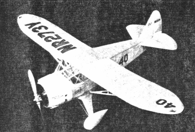
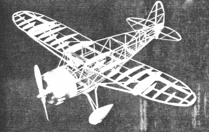
THIS ship won the Thompson trophy at the 1935 National Air Races. We know you will find every minute interesting constructing this trim little racer. It is equipped with several interesting features; shock absorbing landing-gear and movable controls which carry aluminum hinges. This is a 3/4-inch flying scale model and all details carried on the large ship are carefully worked into the model COLOR SCHEME Entire model -- white. CONSTRUCTION OF FUSELAGE First, place waxed paper on top of plan to prevent parts from sticking to it. The fuselage sides are built front 1/16-inch square balsa. The longerons, verticals, diagonal braces, etc., are held in place until securely cemented. This is done by inserting straight pins on either side of strips wherever needed. When the two sides are completed, the crossmernbers are cemented into their proper locations. Cement a 1/16-inch by 1/8-inch piece of balsa to rear of fuselage to obtain the correct width. Check carefully front to rear for alignment. Cut the formers from sheet balsa and cement in their respective positions. Refer to, plan. The sides and top of fuselage are flat. Formers are cemented to bottom and front part of fuselage. Stringers are run over bottom formers. For positions, see plan. Stiff paper is required between 1/8-inch thick balsa nose plate and formers 1, 2 and 3. Refer to photo of framework. CONSTRUCTION OF MOTOR The cylinders are carved and sanded from balsa blocks. When nine cylinders have been formed, wind heavy thread around them to represent fins. Make crankcase from several pieces of balsa. Rocker arm housings, push rods and other small details of motor are made of balsa. CONSTRUCTION OF WINGS To obtain the correct angle between rib F and wing tip, the wing spar and the leading and trailing edges must be cut at rib F. CONSTRUCTION OF ELEVATOR AND RUDDER Elevator and rudder fin are made from 1/16-inch square balsa and constructed on the plan. The lower part of rudder curves outward as shown on former 11, to be of the same cross section as rear fuselage. Cover between formers 11, 13 and 1/16 inch square cross brace with stiff paper. Also cover with stiff paper between former 12 and bottom of fuselage. CONSTRUCTION OF LANDING GEAR After the struts have been cemented together, cement them to the streamline wheel coverings. The wheel coverings are carved from three pieces of balsa and cemented together. Details on plan clearly show shock absorbing arrangement. The model can be built with or without shock absorber; however, we recommend the shock absorber because it prevents damage to undercarriage when landing. COVERING THE MODEL Apply tissue to the various framework members, using a light grade of model airplane dope to fasten it to the outer edges. Stretch tissue as tightly as possible to remove all wrinkles. When edges have dried, apply coat of water to tissue. When all water has dried completely, tissue will become taut. May we suggest that you pin wing, elevator and such to flat surface. This prevents warping. ASSEMBLY After the various parts have been covered, wing panels can be cemented into position. The wing struts are next; these are faired into wing with a streamline fillet made of balsa and stiff paper. The elevator and rudder are cemented to rear fuselage. Scanned from Popular Aviation
|