|
Building The Hornet Complete Data to Build A Low-Drag High-Performance Gas Model That Gets Up Quickly and Stays There By SAL TAIBI
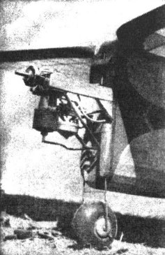
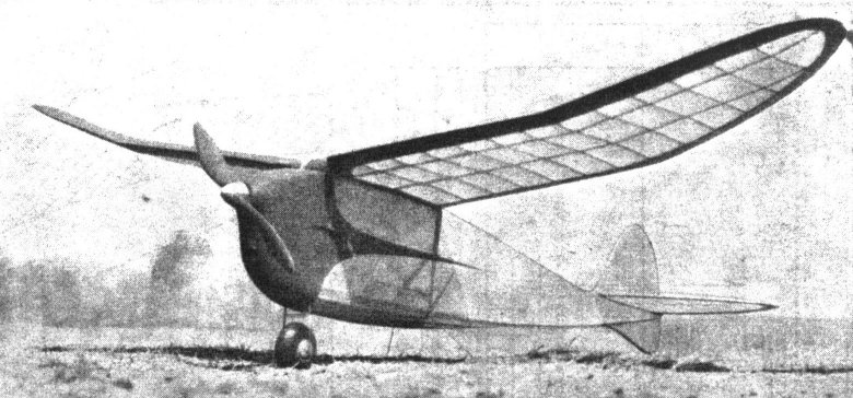
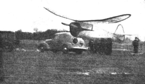
WHEN the Academy of Model Aeronautics met some time ago the 1940 gas model rules were devised and we immediately sat ourselves at the old drawing board and scratched our head in search of a design that would be "tops" under the new regulations. Of course, we're in favor of big ships with plenty of area and a maximum of stability and performance. Those were our prime considerations and the HORNET finally emerged as the plane we wanted. It combines all the features we desired, PLUS streamlining, in a design that is simple to build, easy to adjust and pleasing to the eye. Under power it climbs in a left corkscrew. At the top of the climb it "rolls out" into a flat, level glide to the right. The Hornet really performs like a champion and it's our top ship for 1940. The first test flights were uniformly successful. The first flight, which was made with a 20-second very - low - power motor-run, demonstrated to us that the ship had the inherent stability we had sought and that the glide was perfect. After making minor adjustments, gradual increases in power were made until finally the ship was ready for a real flight . . . and what a performer it proved to be. From a standing start, with absolutely no hand-guidance, the ship amazed all witnesses by consistently doing 1:40 on a TEN SECOND MOTOR RUN. What about a 20-second motor run? Sorry fellows, the ship goes too far and performs too well for it to be risked on test flights, but if you really want to see what it does on a 20-second motor run, we are sure it will live up to this bright promise of long flights. Building and Flying The first step in building the Hornet is to "scale up" the plans to full size. Ordinary bond paper may be used for this process, which may be obtained at any stationery store for about a dime a roll. In scaling up a plan the builder will learn more about the construction of the model than he can in any other way; points of construction which looked complicated in the smaller plates will become perfectly clear when seen in actual size. Scales are given under each particular section . . . some parts have been drawn quarter-size, some full-size, others one-eighth size. Careful study will result in clear, easily understood plans and subsequently in a well-built ship. The Fuselage The first step in building your Hornet is to lay the lower longerons on the plan. (Build two sides at the same time -- that is lay one logeron atop the other.) These bottom longerons, which take a greater part of the shock, are of very hard stock. Top longerons may be of medium stock and it will be noted that these top longerons are doubled at the cabin. After these longerons have been placed on the plan, the A and D braces are inserted and the thrust-line longeron (which is 5/16" x 5/8" stock) is cemented in place. The remainder of the fuselage is of conventional construction and may be easily followed in the plans. After the two sides are built allow them to dry for several hours. While these sections are drying, cut out the main bulkhead (A) from 1/4" birch plywood. The sides of the fuselage are then removed from the board. Assembly starts at this point by placing the bulkhead between the fronts of the fuselage sides and cementing in place. This bulkhead automatically squares up the fuselage assembly. The rear of the fuselage is tapered and cemented and the rest of the braces are cemented in place according to plan. The motor mounts and landing gear are cemented in place. A careful study of the plans will make this process relatively simple. The fuselage skids, of 1/8" wire, are bound to the lower longeron with linen thread and the "tie" is cemented. The bulkheads and stringers are then cemented in place. The sub-rudder is formed and cemented, and as the final fuselage assembly step, the tail skid and tail hook and dowels to hold swing and tail are inserted in proper places and cemented. All joints should be cemented thoroughly at least two or three times. Ignition A carefully wired ignition system will repay the builder many times in efficient operation. The plan should be followed very carefully in this step. All connections should be soldered, as the connections are made on the ignition platform, which is finally cemented into place. Nose Block The nose block is a work of art, but is really simple to build. The center portion is built of 2" x 3-1/8" soft balsa, as shown by dotted lines on the plans. After this has dried it is cut to the solid line outline on the plan. Sides are formed of 5/16" sheet which are cemented in place to complete the cowl. The motor should be mounted before the cowl is finished for your mounting may vary in slight respects. The final interior finishing of the cowl is determined by slipping the block over the nose and letting the motor make an impression on the soft wood of the block. Cuts may then be made to allow better fit, until finally the block rests flush against the fire-wall and the motor is completely enclosed. The hole for the exhaust and adjustment holes for choking and adjusting needle valve may be made. The final forming of the cowl is done with the aid of a sand block, plenty of elbow grease and an eye to the outline on the plan. Final step is a covering of silk, followed by two coats of cement, sanding with 10/0 sandpaper between coats. The cowl is finally given a few coats of clear dope, sanding between each coat and is then ready for the final color dope. Tail Assembly The elevator surfaces are built in the conventional manner. The main spar, the leading and trailing edges are placed on the plan and the ribs (which you will note are NOT cut to an airfoil at this stage) are inserted. After the section has been formed (see isometric view) the entire assembly is cut and sanded to shape. The rudder is built "flat." All edges are cut from 5/16" sheet. The spar and the ribs are of 5/16" stock. When completed the entire assembly is sanded. The Wing The first step in building the wing is the cutting of the trailing edges and tips of 1/4" hard quarter-grain balsa. The wing is built in two halves and tip dihedral is put in after each half is built. The lower leading edge spar is pinned to the board. A half-inch block is placed at the tip and this spar is "cracked" at rib E, this joint being thoroughly cemented. The ribs are then slipped in position. However the rib at the tip-dihedral break is left out in this assembly step to make dihedral forming easier. The two top spars are placed in position and the leading edge is cemented in place on the ribs. The trailing edges and tips are inserted in place, thus completing one half of the wing. Similar steps are used in forming the other half. To obtain the proper tip dihedral, a block 6-3/4" is placed under each wing tip. The quarter-sheet dihedral braces are inserted in the proper position and the assembly should be allowed to dry for at least an hour. After the tip dihedral has been put in the wing halves are joined; the dihedral being formed in the same manner as was done in the tips. Block A is cemented in place and allowed to dry about half an hour, then Block B is inserted. The 1/4" x 3/16" stringers are set in the ribs and the center section is then covered with 1/16" sheet. The original job was covered with yellow paper and trimmed with India red dope; but such color schemes are optional, of course. Don't forget, put plenty of clear dope on the Hornet. This prevents oil-soaking and lengthens the life of the model, besides making for a much neater job. If additional information is needed, or questions arise, write the author care of MODEL AIRPLANE NEWS, sending a stamped, self-addressed envelope. We will gladly try to assist you. Scanned From July, 1940
|