|
We've seen many a one-wheeler in our time, but have never come across one that's as perfect in every detail as this little buggy of "Scotty" Mayors'. Yes, lads, she's got everything that modelers dream about after a good dose of dopeandcementmixedwiththinner - or whatever it is that the medicos jot down in their Latin lingo. But we promise you that this one-legged pretty will chase all of the blues from your system. So get set to build The "Scotch Monoped" By "Scotty" Mayors Designer of "Kiltie Gull Biplane," etc.
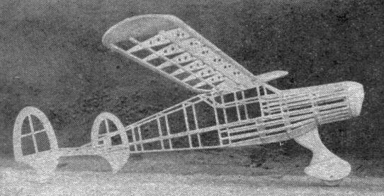
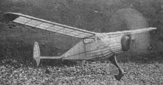
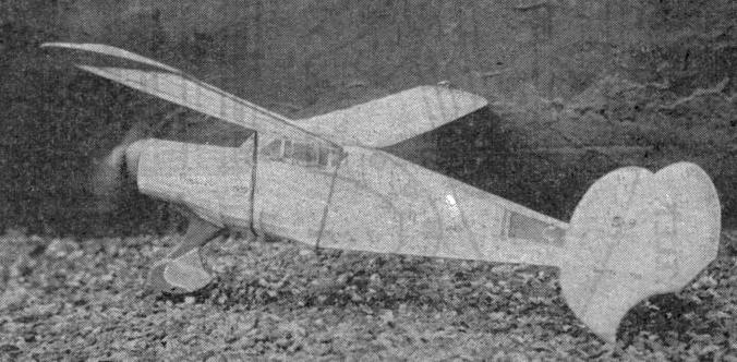
BEING a somewhat canny Scot, my heart was warmed immensely by the thought of the materials, time, money, and labor that would be saved by building a monoped. Hoot Mon! Imagine! Only one wheel, one pant, one landing gear leg, one prop, one wing, one fuselage, and one stabilizer. Alas, it went deeply against my nature to add two rudders, but consolation in the fact that they would balance the plane on the ground and help directional stability in the air eased my conscience. However, not wishing to be too tight, I allowed a fair amount of fin and side area, as was needed, making the model inherently stable in all maneuvers, and easily controlled and flown by the novice as well as the veteran. (And that's the gospel truth, too. But if you doubt me for even a moment, then just stop right here and take a good look at the plans before you go any further.) The model abounds in standard-size wood, no fancy or hard-to-get pieces being used. Provision has been made for easy assembly, all surfaces, including noseblock and landing-gear, having been cut to fit some part of the fuselage. Experiments with a single ski instead of a wheel to be used during the winter should indeed prove interesting. So, unsheath your trusty razor, gather your materials, and build the Scotsman's delight-a monoped! BUILDING THE BODY THE fuselage is constructed entirely of 3/32" sq. and 1/16" flat balsa. Build two sides, as shown by the heavy outline. Connect the top and bottom by crosspieces of 3/32" sq. You will now have a box-like structure upon which to glue the formers, which are cut from 1/16" flat. Note that the formers "1" and "2," "1B" and "2B" are double that is, two pieces of 1/16" flat are cut and laminated to provide the necessary strength. The "keel" fits between former "2B" and the bottom of the fuselage structure. It is cut from 1/16" flat. The cut-outs in the formers provide space for the stringers, which are 3/32" sq. Gussets at the tail-end of the fuselage are cut from 1/16" flat and glued in position. Cross-grain two pieces of 1/16" flat to form the rear hook plug, as shown. No. 12 wire is bent to shape and anchored in the wood. Use plenty of glue to keep both plug and hook in position. Cut and shape the nose-block from a block of balsa 2-1/4" by 1-1/4" by 1". The back of the block conforms to the shape of the front of the fuselage structure. A piece of 1/4" sq. balsa, glued to the back of the nose-block, will serve as a plug, to be inserted in the box-like structure between formers "1" and "1B." The nose is now pierced for the prop shaft, eyelets being glued on the front and rear of the block. LANDING GEAR AND TAIL 0NE landing gear leg, cut from 3 pieces of 1/16" flat balsa, and laminated, may now be made. The cut-out in the middle piece assures a perfect fit on the "keel" of the fuselage. The single pant is cut from 6 pieces of 1/16" flat, the 4 center pieces having cut-outs to allow the wheel to roll smoothly. Sandpaper the pant to a streamline shape, as should also be done to the landing gear leg. A wheel of 1-1/4" diameter is mounted in the pant on an axle of No. 12 wire. Eyelets on each side of the pant will prevent the wire from cutting the wood. Now glue the landing gear leg to the top of the pant. A ridge of glue is advisable where the two parts meet. Glue this unit now to the "keel" between formers "2B" and "3B." The pieces marked "S" are glued to each side of the landing gear leg after it has been glued to the "keel." This makes for strength and easy covering. Tail surfaces should now be built. The stabilizer is constructed of 3/32" sq. with a 1/16" flat trailing edge flap. Round off the leading and trailing edges with sandpaper. Two rudders are built of 3/32" sq. and 1/16" flat as shown. Each rudder may be cut from a single piece of 1/16" flat, the center cut out, and the 3/32" braces glued in place. Sandpaper to a smooth finish. A thin wire skid is cemented to the underside of each rudder to prevent wear on the wood when contact with the ground is made. TO MAKE THE WING CUT 16 ribs from 1/16" flat, carving where necessary to provide for the leading and trailing edge and spars. The size of spars, etc., is given on the drawing. Cut the wingtips to shape and glue in position. To create the dihedral it is best to crack the spars, leading and trailing edges, just to the outside of the center-section, then glue the cracks solidly to provide the 2" dihedral angle on each side. The curved trailing edge at the center-section narrows the wing so that it may be moved on top of the fuselage with no difficulty. A block, preferably of hard balsa, 8" by 1-1/2" by 3/4", is cut to form the prop. Keep the blade section thick, especially near the hub, as one well carved prop is better than a couple of thin toothpicks that break when sneezed at. Pierce a hole in the airscrew to take the prop shaft. And be doubly certain that your prop is carefully balanced. COVERING PROCEDURE PAPER cut in panels and strips, glued to the fuselage with banana oil or heavy dope, will facilitate covering. Tail surfaces may be covered with one large piece for each side. The wing is covered with large panels of tissue, with the grain running lengthwise. Separate pieces are used to cover the wingtips and center-section. Only the first and end rib should be used on the top of the wing for the adherence of the paper, as well as the leading and trailing edge. And the bottom of the wing must be covered by doping the paper to every rib and the spars, in order to maintain the true curvature of the airfoil section. The cut-and-try method is used to cover the cabin and windshield with cellophane. Window outlines may be painted in, the color being left to the model builder's choice. FINAL ASSEMBLY GLUE the rudders onto the tips of the stabilizer in their respective positions. Alignment becomes very important at this phase of assembly, as both rudders must be facing straight ahead, with no deviation from the center line. This unit is now glued to the rear of the fuselage in the position shown. No angle of incidence is used, although there is enough room to provide a slight amount of negative or positive incidence, should this be necessary. The top of the fuselage assures a positive incidence for the wing. Small blocks under the leading edge will increase the incidence. No more than 3 degrees - about 3/16" - should be used. Nine feet of 1/8" flat rubber should be connected between the prop shaft and the rear hook. Cover the hooks with rubber tubing to prevent cutting the rubber motor. The covering should now be sprayed with water to tighten the paper. Two coats of light dope are then applied with a brush or spray. My own personal markings and color scheme are yellow with a contrasting blue scalloped prop and noseblock. License numbers, lettering, and insignia are left to your imagination and ingenuity. FLYING THE MODEL AFTER attaching the 8 strand motor with an "S" hook, try gliding the ship over a smooth landing area, so that you may observe the angle at which she hits the ground. The model should land tail high, gradually settling until the one wheel and two tail skids roll along the ground. Warping the flap at the trailing edge can be used to affect the glide somewhat. During test flights, the Monoped was flown with torque (to the left), and counter torque (to the right). The model climbs rather steeply in either direction, levels out after a 30 second motor run, then floats in very nicely to a "one point landing," settling slowly to the tail skids without the slightest tendency to "wing over" or ground loop. (Continued on page 78) Remainder of article was missing.
Scanned From Dec. 1939
|
|||||