|
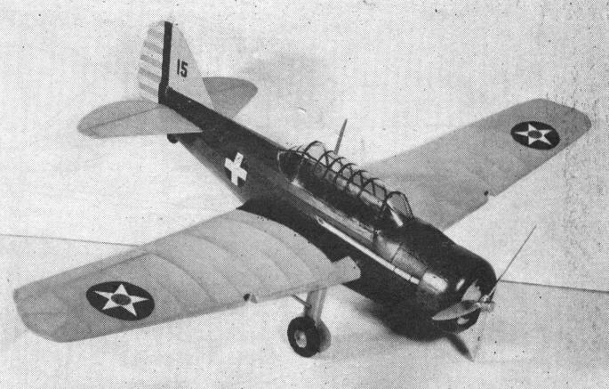
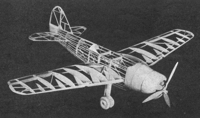
The North American 0-47 Model By
OUR crack Army attack model for this month will thrill you with its long and exciting flights. To make the most of your model, please do not omit any details. COLOR SCHEME Fuselage -- Army Blue. Wings and tail surfaces -- Army Yellow. Details explained on plan. CONSTRUCTION OF FUSELAGE After studying the plan carefully, and you are thoroughly acquainted with details, place a sheet of ordinary wax paper on top of plan to prevent framework from sticking to it. We suggest that you begin with the fuselage, which is constructed one side at a time. The longerons, vertical and diagonal, etc., are held in place until securely cemented. This is done by inserting straight pins on either side of the strips. When the fuselage sides are completed, they are pinned to the top of the plan, in such a manner, that the top longerons face down and the sides are at right angles with the table. The cross members are now cemented in their places, forming a rectangular fuselage. After formers have been attached to the fuselage, the stringers are cemented into position. These are made from 1/32-inch by 1/16-inch balsa, and they are spaced 1/4-inch apart around entire fuselage. CONSTRUCTION OF WINGS This wing is made up of two separate panels. Cut all ribs from 1/16--inch balsa. Pin the spar in position on the plan. Now, cement the ribs in their proper locations. The leading and trailing edges are cut and sanded to shape then cemented to the ribs. The panels carry movable ailerons which are a great help in controlling the flights. Make wing tips from 1/16-inch balsa. We highly approve of this type wing tip, because it is much easier to construct and neater in appearance. CONSTRUCTION OF ELEVATOR AND RUDDER These are made from 1/16-inch square flat balsa and are cemented on the plan. Their construction is easy, therefore, you should have no difficulty here. In covering the elevator, it is important that the two units are covered separately; for they are to be inserted in slot at rear of fuselage. The aluminum hinges are inserted after they have been placed in the rear of the fuselage. CONSTRUCTION OF MOTOR The cylinders are carved from solid balsa and are wrapped with heavy thread to imitate fins. Push rods, etc., are added. CONSTRUCTION OF LANDING GEAR STRUTS Select a tough grade of balsa for landing gear struts. They are reinforced with side struts made from 1/8-inch dowel. All details are clearly shown on the plan. COVERING THE MODEL Do not attempt to cover the model with the framework completely assembled. Cover the wing panels separately as well as other parts. After the framework has been covered, to shrink tissue, apply coat of water. ASSEMBLY Because this model is a mid-wing design, it is necessary to attach the wing panels to 1/8-inch by 1/4-inch balsa beams which pass through the middle of the fuselage. The landing gear struts now are attached, as well as the tail surfaces. The windshield and hood are cemented in position after the model has been completely painted. TESTING AND FLYING Two types of propellers are used on this model. One is made of fiber, which has a much wider blade, causing the rubber motor to turn at less r.p.m., and enabling the model to fly greater distances. By twisting the blades, the pitch can be easily adjusted. The balsa scale propeller is used for exhibition purposes only. Six strands of 1/8-inch flat rubber are sufficient to fly the model. With the rubber motor and flying propeller in place, gently launch your model over tall grass to see whether it is properly balanced. Scanned From July, 1937
|