Building the Douglas 0-43A
by
PAUL W. LINDBERG
Model editor and model designer for POPULAR AVIATION.
|
|
|
BUILDING and flying the model of the Douglas will thrill you from start to finish. Study the plan carefully and note the many new and improved features. All details have been very carefully worked out, and when the model is completed, it represents an exhibition model as well as a flying model.
The ailerons, elevator and rudder have been improved to such an extent that they operate in very much the same manner as those of the larger ships. This is another exclusive feature developed by our laboratory. All dimensions can be quickly and accurately determined by placing a ruler on the parts to be measured. If you wish a larger model, multiply this measurement by the amount of increase.
COLOR SCHEME
Wing and tail surfaces, yellow; fuselage, struts, etc., olive drab; trimmings, red with white pin stripe; other small details, black. See cover of this issue.
CONSTRUCTION OF FUSELAGE
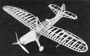
First, place waxed paper on top of plan to prevent parts from sticking to plan. The fuselage sides are built from 1/16-inch square balsa. The longerons, verticals, diagonal braces, etc., are held in place until securely cemented, by inserting straight pins on either side of strips wherever needed.
When the sides are completed, the cross-members are cemented into their proper locations. Check carefully front to rear for alignment. Cut the formers from 1/32-inch sheet balsa and cement in their respective positions as shown on the plan.
The positions of all stringers are clearly shown on the formers. Stiff paper is used in covering top of fuselage from nose to F-4 to F-5 and completely around front of fuselage from nose to former F-9. Do not try to cover in one piece.
CONSTRUCTION OF WINGS
Cut all ribs from 1/32-inch balsa. Pin the spars to position on the plan. Next, cement ribs in their proper locations. The leading and trailing edges are cut and sanded to shape, then cemented to the ribs. Great care should be taken in constructing the ailerons, spars and parts. Carefully shape the spars as shown on plan. The aluminum hinges should be cemented securely to the ailerons before covering. Apply a small amount of cement to other end of hinges, and insert aileron in position after wing and aileron have been completely covered and painted. Make slots, to receive hinges, with a broken razor blade or a sharp knife.
CONSTRUCTION OF ELEVATOR AND RUDDER
The elevator and rudder are streamline, and they require much care in the construction. Cut all ribs from 1/32inch balsa. Build parts upon plan. Fillets for elevator and rudder are made from soft balsa.
CONSTRUCTION OF FILLETS
Cement small pieces of wood to the ends of the wing struts, etc. Carefully sand to shape and reinforce with a small piece of wire. See plan.
CONSTRUCTION 0F EXHAUST PIPES
Select a soft grade of balsa and carefully carve and sand the exhaust pipe, which is built in three sections. The stacks are cemented on separately.
CONSTRUCTION OF LANDING-GEAR
The upper part of landing-gear strut is carved to form a fillet. Next, shape the lower parts of landing-gear struts, making sure that these are reinforced with short lengths of piano wire. Shock absorber is clearly shown on plan. Study details thoroughly.
Apply tissue to the various framework members, using a light grade of model-airplane dope to fasten it to the outer edges. Stretch tissue as tightly as possible to remove all wrinkles. When edges have dried, apply coat of water to tissue. When all water has dried completely, tissue will become taut. May we suggest that you pin wings, elevator and such upon a flat surface to keep from warping.
Next, apply a coat of clear dope to all surfaces. Now, apply colored dopes. Note, do not try to cover frame when it is completely assembled. Wings, elevators, etc., are cemented to fuselage after they have been completely covered with tissue.
ASSEMBLY
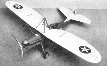
The wings, elevator, rudder, etc., should be cemented in their correct positions. The elevator is braced with two struts running on either side of fuselage outward to elevator. The flying and landing wires are made with a threaded needle which you force through the balsa. Thread is held in position with a drop of cement. The position of all spreader bars is clearly shown on photograph of finished model.
Two types of propellers are shown on the plan. The flying propeller, which has fiber blades, has less r.p.m., in order that the model can fly a greater distance. Plenty of patience is required to construct the propeller. It should be carefully adjusted until the best results are obtained. Four to six strands of 1/8-inch flat rubber are sufficient to fly the model. To balance the model, a small amount of weight can be added to the nose.