The Moffett Trophy Winner
AIR TRAILS presents plans and instructions for building the New Zealand model that flew 44 minutes and 14 seconds
prepared by Gordon S. Light in collaboration with Vernon Gray
|
|
|
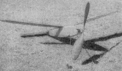
Gray's well‑designed 1936 Moffett International winner.
MANY years ago all the world's troubles were tightly locked in a box. Every one was happy,
until some inquisitive person, anxious to see what was inside, opened the box and released the evil spirits. This was the beginning of the world's troubles. Ever since then conscientious people have tried unsuccessfully to get these spirits back into the box.
This fable of Pandora's box applies to model building. Before July, 1936, we had the Moffett International Trophy, and peace and quiet existed throughout the model world. And then, without warning, some one opened the box containing Vernon Gray's Moffett entry. Instead of an evil spirit, however, a well built and cleverly designed model flew out of the box. Up and away it soared as though it seemed glad to be free after its 30‑day trip from New Zealand. As quickly as possible the model was recaptured and put back into the box. But the damage done in that short time will take at least a year for us to repair.
But if Bert Pond had not opened Gray's box last July, we would have missed one of the year's outstanding models. Since it turned in such an excellent flight, we can forgive the damage it has done and cheerfully set about regaining the trophy in 1937.
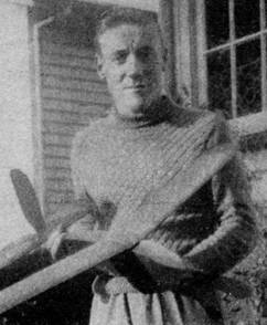
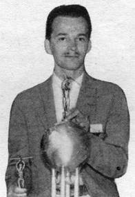
Before examining the features of this remarkable model and starting work on a replica, we should know more about its capable designer and builder, who is holding the Moffett Trophy for a year. Vernon is 21 years old, and has had five years of modeling experience. Strangely enough, he has concentrated mostly on indoor models, and at present holds three New Zealand records. In 1935 he took up outdoor models seriously by sending an entry to the Moffett contest in St. Louis. This model had a good climb, but was tricky to adjust and fly. Despite the good work of the American proxy flier, it placed seventh with a rather poor flight of only 1 minute 18 seconds.
Building on the knowledge and experience of 1935, Gray built a ship that would be easy to handle and simple to fly. As Gray himself puts it, "The design is clean and straightforward, and above all, the model is a consistent flier." Proof of this is the winning flight of 44 minutes 14 seconds which Bert Pond, proxy flier, turned in at Detroit after several short trial flights.
The model follows closely the American formula for good flights. The large 16‑inch propeller is shaped and carved in the way we're used to doing it. Likewise the lifting elevator parallels our designs closely. It is interesting to think that the same practices in model building have spread throughout the world. Regardless of nationality and country, we all speak a common language of propeller sizes and wing shapes.
And now for actual construction. The plans and instructions for building have been prepared from data supplied by Gray. Every detail is shown as it appeared on the original ship. Incidentally, last month in announcing these plans, they were incorrectly referred to as those of the winning Stout Trophy model. The Stout model, like the Moffett, is open to cabin fuselages. However, it is not an international contest like the Moffett.
FUSELAGE
The fuselage is of simple square cross section. Only the side view of the fuselage has been included in the plans, since the top view is identical to it. Build two fuselage sides at the same time from 1/8 x 1/8" balsa longerons. After they've completely dried, put in the cross braces. On the fifth upright, cement a piece of 1/8 x 1/2" balsa at a slight angle to give forward slant to the landing gear struts. The struts are bamboo 1/16 x 1/8 x 8‑1/2". They can be cemented directly to the balsa. Or if you wish to have a demountable landing gear, cement spaghetti‑tube sockets to the balsa cross brace. Balsa fillets s are added to strengthen the fuselage at this point. The tread of the landing gear is 9".
The fuselage separates at the rear to permit handling of the rubber. The rear hook is attached to the rear section of the fuselage. Fasten the hook to a cross brace of 3/16 x 1/4" balsa. The nose of the model back to the first upright brace is covered with 1/16" sheet balsa. Likewise the two sides of the fuselage at the extreme rear are covered with 1/16" sheet to provide a substantial attachment place for the elevator.
Fuselage construction is completed by adding wire axles to the ends of the landing struts and slipping on a pair of 1-1/2" diameter wheels built up of three sheets of 1/16" balsa .cemented together with the grains crossed. A 5-1/2" tail skid of 1/16 x 1/16" bamboo is added at the position indicated in the drawing.
WING
The rib section is one familiar to all of us. It is the Clark Y. The bottom surface is flat and the maximum camber is slightly more than 11 per cent. It is shown full size in the drawings. Cut 24 ribs from 1/20" sheet and cut out the notch for the leading edge, 1/8 x 1/8", and the spar, which is 9/32 x 5/64". Mark the rib positions and then slide the ribs onto the spar. Line up the ribs and cement them in place. Add the 1/8 x 3/8" trailing edge to the rear ends of the ribs. The leading edge is of hard balsa, and cemented to the front of the ribs. The wing tips are bent from 1/16 x 1/16" bamboo to a graceful curve. When attaching these to the ends of the wing, it will be necessary to cut portions off the front and rear of each end rib. After this has been done and the tips are firmly cemented, sand down the end ribs so they fit into the bamboo tips.
Dihedral is added by breaking the wing at each side of the center section. The center section itself is flat. Raise each tip 3-1/2" and add cement to strengthen the break. Finally add the balsa fillets as additional strengtheners.
TAIL
The one‑piece elevator is constructed like the wing. Ribs, shown full size, are cut from 1/20" sheet. Necessary dimensions are available from the drawing. The fuselage is cut away to receive the elevator.
The rudder shape is shown reduced. To reproduce this shape, line off a sheet of paper into squares. Locate the points on this drawing which correspond to those on the reduced drawing.
The rudder is built in two pieces. The top rear section is movable. It is hinged to the main rudder structure with two short lengths of soft copper wire. The rudder ribs are simple streamline shape. That is, they are about 3/16" at the center and curved toward the front and the rear. The leading and trailing edges are cut from hard 1/16" sheet balsa. The pieces fit edgewise to the ends of the ribs.
PROPELLER
The propeller is carved from a block 1‑3/4 x 1‑5/8 x 16". Use medium balsa. Carve so the blade is 1/4" thick at the widest part, tapering to about 1/16" at the tips. Cover with superfine paper, add a coat of dope and smooth with fine sandpaper.
FREE‑WHEELING
We thought we had seen all types of tree‑wheeling until Gray sprang this one on us. It is a clever method, and not at all difficult. Look at the drawing showing the free‑wheeling detail. Here the propeller is shown enlarged. First cut two washers of 5/16" radius from .01" tin steel. (Ordinary tin‑can metal will do nicely.) These washers are slotted and bent as those in the drawing. One washer is soldered to the end of the propeller shaft. The other washer is soldered to a thin strip of copper sheeting which is wrapped around the hub of the propeller. Incidentally, when soldering the washers, place a sheet of paper between them to prevent soldering them together.
When the rubber is wound, it pulls the outside washer up against the washer on the propeller and engages the propeller. After the tension is relaxed, the washers no longer engage, but allow the propeller to spin free.
COVERING
The fuselage is covered with yellow paper. Water spray it and apply two or three coats of clear weak dope. Cover the wing with red tissue. Repeat the spraying operation and follow with two coats of weak dope. The permanent part of the rudder is yellow and the movable portion is red. The elevator is covered with yellow tissue. Both the elevator and rudder covering are treated with water spray and dope. The landing struts are painted black. The propeller is given four coats of black lacquer, with a rubdown between coats.
ASSEMBLY
Put a 3/16" block of balsa under the front edge of the wing and fair it into the rib profile. The curved top of the fuselage necessitates changing the thickness of this block to fit the particular section of the fuselage where it is attached. Incidence of 3 degrees is the correct setting for the wing. The wing shown is set at this angle. Rubber bands hold it to the fuselage.
The elevator is set at 1 degree negative angle. (Shown correctly in the drawing.) Before cementing, make sure the elevator lines up with the fuselage and the wing. The rudder is cemented to the top rear of the fuselage and the top of the elevators. It is strengthened with 1/32" square bamboo braces extending from the center of the first rubber rib to the first elevator rib on each side of the fuselage. Ready to fly, the model weighs 2-3/4 to 2‑7/8 ounces.
FLYING
Put 16 strands of 1/16 x 1/8" rubber intro the model Brown rubber is used. When inserting the nose plug, make sure the propeller shaft points down and to the right. Glide the model a few times until a floating glide is obtained. Then try it under power. With about 250 turns, the model should "grab" about 100 feet of altitude and complete several right circles, landing in a nice glide.
Now wind the motor tighter‑‑from 400 to 900 turns. If you're afraid of losing the model in a current, fit the nose plug loosely so it will drop out after the motor is unwound. This will handicap the glide and the model will settle to the ground. With only 400 turns, Gray's ship flies 45 seconds under power and after the propeller stops glides for 1 minute.
SUMMARY OF DESIGN
Gray has been kind enough to send us some of his ideas on model design. Here are his comments:
"To be a place winner in a contest, your model must combine the following points‑stability, consistency, power, and gliding and soaring abilities. I say consistency as applying to one's self more than the plane. You've got to know your plane. If your model is stable, it will give consistent flights providing you're up to scratch.
"The free‑wheeler is a necessity. The next step from free‑wheeling is a folding propeller. The free‑wheeler described in this article has been used by me from the start. It is simple and clean.
"Wing is of clean design. I prefer parallel wings in the respect that there is less area at the fuselage to be affected by air disturbances. It is easy to build, as all the ribs have the same profile. In a taper wing, 90 to 100 per cent of the chaps draw out the tip and root ribs, possibly one or two of the others, and then they contend that their tapered wing is more efficient than your accurately constructed parallel wing.
"Fuselages in the future designs can be improved a great deal. This model was built in a hurry for the 1936 contest. I intended to use a round fuselage with a spinner on the propeller. Even better would be a fuselage with an elliptical cross section. The undercarriage on this model is simplicity itself, light in weight, and stands the gaff with little resistance to hinder the model."
After you've built and flown Gay's model you'll realize fully the soundness of Gray's ideas. Personally, we're very glad he won the trophy. And if we can't persuade it to return to the United States during 1937, we hope that Gray will continue to be its custodian during its sojourn in New Zealand.