The Plan Page
[ Home ] [ Previous Plan Pages ]
[ Special Things ] [ Earl Stahl Plans ]
Arctic Flier
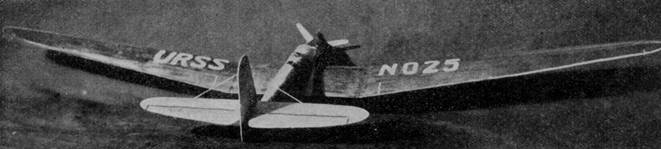
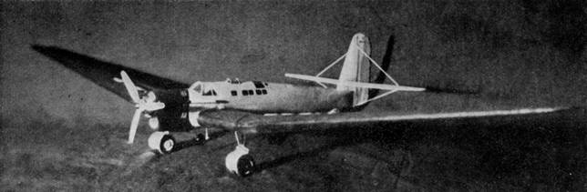
A. N. T. 25
The long‑winged Russian plane on the cover comes to America in an unusual flying scale model
by Alan D. Booton
And now let us see what we can do with a flying model of the A.N.T. 25. The most noticeable feature is the high‑aspect ratio of the wing which, in relationship to the seemingly conventional fuselage, would cause most model builders to think twice before attempting a flying model.
The A.N.T. is of all‑metal construction, chrome aluminum and steel, covered with 24ST, so in the model we will try to conform with the all‑metal appearance by using all‑balsa construction. Since the trend of large planes is toward the all-metal type, why shouldn't we use a medium to reproduce the miniatures to be the envy of the large planes ? The A.N.T. all‑balsa construction is really quite simple, if care is taken with the consecutive steps of building. Ready to fly, the model weighs less than 2 ounces.
Read the instructions carefully and study the drawings before starting the model.
FUSELAGE
The first step is to make a 1/16" thick sheet of ply balsa 4 x 6" to provide formers. Weigh it down and let dry at least for an hour.
The cowl is made from a block and extends from the nose block to 1/32" back of the center‑section spar. Transfer the over‑all side‑view outline (less windshield) to the side of the block, then cut the outside portion away. Transfer the top view to the top of the block and cut again. If carving is difficult for you, make cardboard templates to fit the outsides of sections 1 ‑ 4 on drawing #4 to use as the cowl is carved. Sand the cowl and then hollow it to the approximate sections. Carve a nose block to fit the cowl and insert a bearing tube to have the proper down‑thrust.
Mark the former locations on the two side longerons and cement them in slots on the cowl. Arrange them so they will dry parallel and on the center line.
Cut out of the plywood sheet a pair of each of the formers, 4a‑8, and cement them together. Former 9 is cut out of 1/16" sheet balsa, and is equipped with the rear hook, as shown on drawing #2. Start with former 9 and cement the formers to the side longerons toward the front. When dry, add the top and bottom longerons.
Now comes the job you may think difficult. Instead of using tissue, cover the fuselage with 1/64" sheet balsa. Cut a trial pattern for one side out of paper, starting at former 4. The two balsa patterns are then cut and cemented on, working back to 9. Apply cement to each former and longeron as you proceed. Rubber bands and pins are a great aid in holding the balsa patterns in place. Check up at each former to see that the frame has not warped out of line.
Note: the fuselage side patterns can be pre‑curved by rubbing a thin layer of cement on the inside of each.
The center section is made integral with the fuselage. Make the center-section spar, the trailing edge, and the two leading‑edge parts and mark the rib spacing on them before cementing them to the fuselage.
Cut six of the whole center‑section ribs and two of the partial ribs. Cement the two outer ribs on first to line the spar and edges up, and then add the other ribs.
The landing gear must be attached at this time. Fit the parts as shown between the outer ribs and then attach the 1/8” aluminum tube and braces. Dowel rods, bearing the double‑wheel axles, are trimmed to slide tightly in the aluminum tube. When the flying propeller is used, the dowels can be extended to allow for the long blades, and forced back when the scale propeller is desired. The metal fenders or fairings are made from .550 sheet aluminum as per drawing #4.
Cover the center section from outer to inner ribs with 1/64” sheet and add the rear fairings for the wheel trucks. Carve the dummy tail wheel and fairing assembly and cement in place. Cement the celluloid windshield patterns on the cockpit and over the relief pilot enclosure. Make the exhaust stack and heater units from 1/8" dowel rod and cement them in place. The cabin windows may be cut out and fitted with celluloid, or just painted black when coloring the model.
WING AND TAIL
The wing panels and tail surfaces are of unusual construction. On drawing #1 the cover patterns and ribs are complete. Cut a pair of each rib and cover. Mark the rib spacing on the lower cover patterns and on the 1/16 x 1/8" leading edges. Cement the ribs to the leading edges first and then to the lower pattern with cement on a 1/2" space at the rear of each rib, because the pattern will only touch the ribs at the rear while pinned to the board. Pin the rear of each rib firmly to the lower pattern. Be sure the first rib has the right angle to obtain the 2" dihedral.
Now cement the remaining portions of the ribs toward the front and along the leading edges. The scraps that remained from the rib cutting will come in handy to wedge the bottom pattern up to the raised leading edges and rib bottoms. Note that the first rib leading edges are high, while those at the tips are low. The wash‑out is essential in this model to prevent the addition of weight to the nose.
Trim the lower pattern along the center of the 1/16 x 1/8" strip when dry. To apply the top cover pattern, cement its trailing edge to the lower trailing edge, sparingly. When dry, apply cement to all ribs and leading edges and press the covers on firmly, using pins where necessary. When dry, remove from the board and true up with fine sandpaper.
Assemble the tail surfaces in the same manner as the wings.
PROPELLERS
Two views of the scale prop blade are shown on drawing #3. Three are inserted in the scale spinner.
The flying propeller is also three bladed, and very wide to provide sufficient thrust. Blank the blocks as per front view and cement them together, then carve to obtain the spinner and diminished hub. Insert the shaft in the usual manner, and provide several washers to cut down friction.
COMPLETING THE MODEL
Cement the wing panels and tail surfaces in position on the fuselage.
When coloring the model, do not use dopes, because they are apt to warp the thin balsa covering. Thinned lacquer is recommended; use a coat of thin, clear lacquer first.
The fuselage, tail surfaces, and propellers are gray or aluminum. The cowl, landing gear, tires, cabin windows, and small lettering, black. The wings are red from fillets to tips, with aluminum or gray URSS letters 1-1/2' high on the top of the left wing and bottom of the right, and N025 on top of the right and bottom of the left. Trim the pilot's cockpit shield with gray or aluminum. Fit the model with the remaining detail.
FLYING THE MODEL
Power the model with 8 strands of 1/8" flat, lubricated rubber. To get the rubber into the model, bind the rear end of the motor and insert an "S" hook. Hold the nose of the model upright, and drop the rear of the motor into the fuselage and fish for the rear hook. Glide the model in tall grass, or wind the motor just enough for it to take off. If the model has a tendency to stall, especially on a glide, add incidence to the stabilizer.
MATERIALS
|
1 |
1‑5/8 x 2 x 3‑1/16" cowl block |
|
3 |
5/8 x 1‑1/2 x 4" prop blocks |
|
1 |
1/4 x 1-1/8x1-1/8 " nose block |
|
14 sheets |
1/64 x 2 x 18" |
|
1 sheet |
1/32 x 2 x 18" |
|
2 sheets |
1/16 x 2 x 18" |
|
4 |
1/16 sq. x18" |
|
2 |
1/16 x 1/8 x 18” |
|
1 oz. |
cement |
|
1/2 oz. |
gray lacquer |
|
1/2 oz. |
red lacquer |
|
1 oz. |
Clear lacquer |
|
2 drams |
black lacquer |
|
2 oz. |
thinner |
|
|
4" 1/8 alum. Tube, 1 x 3 .005 sheet alum., 1 x 3 celluloid, bamboo, 4" 1/8 dowel rod, thread, #12 music wire, 1/l16 alum. tube, 80" flat rubber. |
Scanned From December 1936
Air Trails
![]()
![]()
![]()
![]()
[ Home ] [ Previous Plan Pages ] [ Special
Things ] [ Earl Stahl Plans ]