The Plan Page
[ Home ] [ Previous Plan Pages ]
[ Special Things ] [ Earl Stahl Plans ]
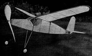
The ZEPHYR
Lightweight
One‑half ounce of
flying fun for the
beginner that will ride the slightest breeze.
THE Zephyr gets its name from its ability to ride very slight up‑currents of air for long flights. The weight of this little model is only .52 ounces, and the wing area 82 square inches, giving a wing loading of .32 ounces per 50 square inches. This loading is too low for contests, but the Zephyr is easier to fly than heavier models. It's not sensitive to wing or elevator settings. If it dives into the ground during preliminary flights, the extremely light weight will prevent serious damage. In short, an excellent model for the beginner tackling his first fuselage job.
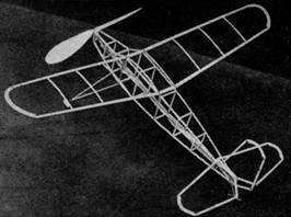
Light weight is obtained by simple construction. The wing is single‑surfaced ‑ covered on the top side ‑ and the elevator and rudder likewise. The fuselage, built from 3/32" square balsa longerons, is the most rugged part. It must be strong enough to absorb the strain of the rubber motor, which is attached directly to the fuselage.
The landing gear is designed to fit the floats which were described in the October issue of AIR TRAILS. If built slightly more sturdily, with a few additional strands of rubber, the Zephyr will make a fine hydro model.
It can be flown indoors in your high‑school gymnasium or auditorium. Two‑minute flights should be easy. If you intend to do much indoor flying, lighten the construction. The weight can be reduced as low as .25 oz. by using lighter fuselage structure, less rubber, paper-thin propeller, and lighter tail. A quarter‑ounce model can be flown outdoors in calm, dry air. A model of this weight needs only a suggestion of an upward air current to carry it away. In fact, our model is so sensitive to currents that I have seen a gust of air pick up the wing of the dis‑assembled model and carry it out of sight, high in the sky.
Even if the Zephyr does decide to go away on a rising current, you'll enjoy all the thrills of a long flight without the pain of losing an expensive and hard‑to‑build plane. The Zephyr can be built with little time and expense, and offers an ideal way of experimenting with thermal current flying.
PROPELLER
The propeller is the most important part of the model, and unfortunately the most difficult to make. For this reason, let's tackle it first while your knife is still sharp and your enthusiasm high. The block size is 7/8 x 1 x 9", giving a pitch of 12-1/2", a value which falls close to the generally accepted pitch‑to‑diameter ratio of 1-1/2.
After rough‑cutting the propeller with a knife (some builders find a small plane helpful) the blades are sanded thin enough to permit light to pass through and to bend back or forth at least 1". A propeller cut from soft balsa with a thick hub and thin blades weighs about .15 oz.
FUSELAGE
The full‑size fuselage is given in the drawing. The top view has been omitted; instead, the dimensions noted at each cross‑brace position indicate the width of the fuselage at that point. The dimension given is the overall width ‑ the cross brace itself is cut 3/16" less than the dimension to allow for the thickness of the two fuselage longerons.
The rear post, 1/8 x 1/4" serves as the mounting for the rubber hook and rudder.
There are two ways of obtaining the shape of the cabin window which is visible in the photo. You can add cross braces of 3/32 x 3/32" balsa to serve as the window outline and cement the cellophane to them, or you can lighten the weight of the fuselage by omitting the cross braces (as has been done in the drawing) and cementing the cellophane directly to the cut‑out tissue covering of the fuselage.
LANDING GEAR
The bamboo landing gear is easily made. Select two 12" pieces, bend them as shown in the sketch, and join the ends with thread and cement. After you've wrapped the first few turns of thread, cement the bent wire axles to the ends and then add several additional loops of thread to hold them in place.
One interesting feature of the model is the paper wheels. These were widely used a few years ago, but have been replaced by balsa wheels. There is no apparent reason for this loss in popularity, since paper wheels are as easy to make as balsa wheels, and are usually smoother running. Stiff writing paper should be used. A pencil compass is the only tool you'll need, besides a pair of scissors.
With the compass set at 5/8” radius, lay out four circles. Cut out carefully. Next cut each circle along a radius. That is, cut a straight line between edge and center. Overlap the cut edges of each disk 1/8", cementing each paper circle into a shallow cone. The wheel is completed by joining two of these cones. Cement the edges and press lightly together. Slip the wheel on a piece of scrap wire and line it up while the cement is still pliable. A drop of cement on the center of each half of the wheel will make a smooth bearing surface and prevent the axle from tearing through the paper.
WING AND TAIL
The cambered wing ribs, of shape shown in the fuselage drawing, are cut from 3/32" sheet balsa. The camber is cut into them, as it is difficult to bend ribs so they retain their shape. The wing spars of the wing are tapered from 1/16 x 1/4" at the center to a tip size of 1/16 x 1/8". A metal rule and a razor blade will do this nicely. A good procedure for wing‑building is to work on a flat board or work bench. Add dihedral after the wing has been completely assembled. Some builders prefer to make the wing in one piece and then crack‑and‑cement the spars to add the dihedral. Others build the wing in two halves and join them with short lengths of spar material just long enough to fit over the top of the fuselage. By making the wing in two halves, you'll be able to use the same drawing for both halves. Light wire hooks are set in the spars for the rubber‑band attachments to the fuselage.
The elevator and rudder are of extremely light construction. The elevator is flat and covered on top. The rudder, likewise, is flat. Use 1/16 x 1/8 " balsa in both. If you're planning to give the model a rigorous flying schedule, such as flying in gusty air or as a hydro, strengthen the elevator with a spar running lengthwise through the center and "beef up" the rudder with a similar spar.
COVERING
Applying tissue covering on a lightweight model that can't be treated with dope or water‑spray is a task that troubles the best of us. Select superfine tissue and iron out the wrinkles. Run the grain lengthwise along the wing and fuselage. Cover the wing in three sections - each half and the center section.
A good technique is to lay the tissue on the wing and pin the corners lightly to the spars. Next secure the corners with banana oil. Fasten the tissue to every part of the spar as soon as you've satisfied yourself that you've removed all bagginess in the tissue. Don't fasten the tissue to any ribs other than the two center ones. The fuselage covering should be banana‑oiled to every part of the framework which it contacts.
The wing and tail surfaces are too weak for doping or spraying, but the fuselage tissue can be tightened by a light water spray. Don't be worried about wrinkles that appear in the wing and tail. The air moisture absorbed by the tissue over a period of time will be sufficient to shrink it. This operation can be speeded up by moistening with steam, but be careful ‑ a thorough soaking by steam will be as damaging as spraying with water.
FLYING
The motor is four strands of 1/8 x 1/32" rubber. It fits on to a wire shaft inserted through the nosing and the prop; the rear is attached to an "S" hook. Straight wire is useful in pulling the motor through the fuselage. A wire clothes hanger can be converted into a satisfactory winding hook. Winding is done through the uncovered section at the rear of the fuselage. As a safety measure, some builders like to wind the motor outside the fuselage, where it can't cause damage in case it breaks. After the motor is tightly wound, pull it through the fuselage with the winding hook.
The rectangular nose plug consists of pieces of balsa sheet cemented together, the inner piece fitting between the nose cross braces. It is likely to become worn after a time and fall out when the rubber is slack. The propeller hanging loose at the front of the model naturally reduces the glide. Pin the plug in position for long flights. However, when you're testing your model, let the plug fall out and the decreased soaring ability of the model will insure its return for future flights.
Cement the elevator and rudder permanently atop the rear of the fuselage. The settings of both these surfaces can he changed by warping the rear edge, which is done by breathing over the tissue and gently twisting the framework. Make all major adjustments by sliding the wing backward or forward. Negative or downward prop thrust may be useful, but it is hardly necessary if you take reasonable care in balancing the model. The slight stalling tendency usually shown by lightweight models will not reduce the length of flight.
WEIGHTS
| Wing | .08 ounces |
| Prop, nose plug, shaft, etc. | .19 ounces |
| Rubber | .15 ounces |
| Fuselage, elevator, wheels, rudder | .10 ounces |
| Total R. T. F. | .52 ounces |
MATERIAL
| 8 | balsa fuselage longerons and braces 3/32 x 3/32 x 18" |
| 2 | bamboo landing‑gear struts 1/32 x 1/16 x 12” |
| 1/16" sheet balsa for ribs, tips, and plug | |
| 4 | balsa strips for elevator and rudder 1/16 x 1/8 x 12" |
| 1 | balsa propeller block 7/8 x 1 x 9" |
| 4 | spars tapering from 1/16 x 1/4" to 1/16 x 1/8" x 12" long |
| small sheet of superfine tissue, cellophane, and stiff paper for wheels | |
| short length of wire, several washers | |
| 6 ft. | 1/8 x 1/32" rubber |
| cement and banana oil |
Scanned From November 1936
Air Trails
![]()
![]()
[ Home ] [ Previous Plan Pages ] [ Special
Things ] [ Earl Stahl Plans ]