|
|
The MODEL |
The Plan Page
[ Home ] [ Previous Plan Pages ]
[ Special Things ] [ Earl Stahl Plans ]
|
|
The MODEL |
Build and Fly
the SKY FLEA
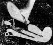
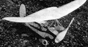
Two views of the
finished model.
MY first view of the Flying Flea was in a hangar at Roosevelt Field, where it was nestled under the wing of a neighboring monoplane. The 19 foot wing of the Flea would seem small under any conditions, but such a direct comparison to the large‑size airplane made it seem even smaller than it really is. It seemed as though it was just a model that could be picked up and glided like any other model airplane. A closer inspection showed that despite its midget proportions, the Flea is rugged and airworthy.
One notices at first glance the outstanding difference between the Flea and the conventional airplane. It is the use of two large wings instead of the usual tail and wing. This theory of tandem wings is one that every modeler should thoroughly investigate. The Flea startled the aviation world with a successful application of this idea. A successful tandem wing contest model would have the same effect on the model world.
A tandem wing model will have the benefit of a much lighter wing loading and still be eligible for contests. The weight required will be determined by the area of the main wing. In other words, the Flea, according to N.A.A. rules, would be required to weigh only 1.88 ounces, since the area of the front wing is 94 square inches. This is at the official rate of one ounce for every 50 square inches. But the rear wing adds 59 square inches more of lifting area that does not have to carry additional weight. This would give the tandem wing model a distinct advantage.
The tandem wing idea has been partially developed in the theory underlying most of the designs presented in this department. In our contest ships we've always used a lifting tail that ranged about 30 per cent of the main wing area. The elevator area of the Wakefield Winner presented in the April issue of Bill Barnes‑AIR TRAILS was 32 per cent of the wing. However, in these models there always was sufficient length between the wing and elevator to provide good stability. In the Flea this distance between wings is short ‑ 6-1/2" ‑ which is only 27 per cent of the wing span. The Wakefield Model had an effective coupling of 47 per cent of the span.
By careful designing, however, we could cut down the distance between the wing and tail. A step in this direction was the Sockdolager in the November issue. This model had a coupling length of 31 per cent of the span and a tail area of 30 per cent of the main wing area. This model was stable under all flight conditions and gave an excellent account of itself in duration flying. But a truly tandem wing model would be one with a rear wing of at least 50 per cent of the main wing area. Experiments along these lines would be a great deal of aeronautical fun.
IN BUILDING the model of the Flea, the general outline and characteristics were followed. Wherever possible, the exact dimensions were scaled down. The scale of our model is about 1-1/4" to the foot, or a little over one‑tenth of the size of the real plane. But several modifications of design were necessary in order to make the model flyable. The value of making these changes was shown by the splendid performance of our Flea. It proved to be an airworthy model ‑ one that can he truthfully called a flying model.
The duration was short, since the rubber length is only 11 inches. By using a winder, however, we managed to store enough turns in the short motor to get 30‑second flights. And what flights they were! Steep climb, half a dozen circles at 25 to 30 foot altitudes, and a smooth glide back to earth with a dead motor.
One point of design which has a serious effect on the flying qualities is the upturned trailing edge of the wings. In both rib shapes ‑ front and rear wing – you’ll notice that the rear tip of the rib is turned tip. By shaping the ribs in this fashion you can save the Flea from the life of stalls and dives that it would experience with the ordinary flat‑bottomed rib shape, and make stable flights possible.
The characteristics of the Flea are such that 18/100ths ounces of lead had to be added to the nose of the model to balance it. This brought the total weight to 1.25 ounces. However, this makes the wing loading only 1 ounce for every 123 square inches of area. This is still a light loading. So if someone can design a contest version of the Flea, they'll have the advantage of light wing loading. On the other hand, they'll have trouble in getting a rubber motor of sufficient length to keep the propeller turning for a competitive length of time.
But before we think too far ahead of making a contest model, let's build this original version of the Flea and see what success we have. The construction is not difficult. Little material is required. So let's go!
MATERIAL REQUIRED
12 pcs.
balsa 3/32 x 3/32 x 26" for fuselage and wings
2 pcs.
3/32 x 3/16 x 24" for trailing edges of wings
2 pcs
sheet balsa 1/32 x 2 x 24" for covering front of fuselage
1 pc
sheet balsa 1/8 x 3 x 2" for curved bottom of fuselage and tail wheels
1 pc
balsa block 1-1/4 x 1-1/4 x 2-3/8" for cutting engine nosing (labeled "A" in drawing # 1),
1
balsa propeller block 3/4 x 1-1/4 x 7",
2
large sheets of tissue
1 pr
1-1/2" diameter wheels
1
small bottle of cement and 1 of banana oil
several brass washers to reduce bearing friction,
2 feet
of medium wire for wing support, propeller shaft, rear hook, etc.
CONSTRUCTION
The Flea has been drawn full size. Study the five drawings until you have a clear idea of what is required. Drawings #1 and #2 should be joined together to form a complete fuselage layout. The fuselage should be built first. Balsa 3/32 x 3/32" is used throughout. In making the fuselage, you can work directly from the drawing. That is, shape your wood the size it's shown in the full‑size drawing.
The bottom front of the fuselage is shaped by two curved portions cut from 1/8" flat balsa.
Notice that the entire front of the fuselage is covered with 1/32" sleet balsa. This added weight serves a twofold purpose ‑ it strengthens the fuselage where there is great strain and helps balance the model by bringing the center of gravity nearer the front.
In drawing #1, the balsa nosing which substitutes for the two‑cylinder motor used on the large Flea is labeled "A." This is cut from balsa, and the inside is gouged out to allow the rubber motor and propeller shaft to pass through. In drawing #4, the four steps in cutting this nosing are explained.
In step 1, lay off the block as indicated by the solid black lines. Cut away the excess balsa and sand the block smooth as in step 2. Next cut the block in half lengthwise through the center. This has been done in step 3. Cut away the inside of the block to allow the propeller shaft to turn freely. The bottom of the noising is cut open so the rubber motor can be attached to the propeller shaft. After you've cut away the inside portion of each half, cement the pieces back together again. If you're expert with it carving knife, it might not be necessary to cut the nosing in half in order to hollow it out. However, it is an easy method and after the pieces are cemented together you'll barely be able to pick out the joint.
Mounting the propeller and the rubber motor is shown clearly in drawing #1. The propeller had to be lowered to permit the rubber to run through the top of the fuselage, but this did not handicap the Flea in flying or appearance.
The balsa engine nosing "A" and described above is fastened to the fuselage with 3/32 x 3/32 balsa supports. Three pairs of braces give plenty of rigidity to withstand the pull of a four‑strand motor. A washer cemented to the front of this noising provides a propeller bearing. You can use either a punched clothing snap or a cup‑washer. These are available with protruding prongs that can be inserted into the balsa to keep the washer in position. Be sure to add a touch of cement as an additional precaution against the washer coming loose.
In the construction of the fuselage it was impossible to leave an open space for the cockpit. The tension of the rubber made the addition of braces necessary. The two braces identified as "B" in drawing #1 run alongside the rubber motor and strengthen the fuselage.
The rear end of the rubber is attached to the rear of the fuselage by a wire hook cemented and threaded to the rear fuselage post.
In drawings #2 and #4 are shown the details of tail wheel construction. The two 1/2" diameter tail wheels are cut from 1/8" balsa. A wire axle joins the wheels. Notice that it is cemented rigidly to the wheels. Thus both the axle and the wheels revolve. The tail wheel is attached to the fuselage with one vertical strut running to the rudder post and two horizontal struts attached to the bottom of the fuselage.
The front landing gear is easily attached by cementing and threading a 5" piece of wire to the lower longerons in the position shown in drawing #1. About 1/2" from each end of the wire cement a small piece of balsa wood to the axle. This serves as a wheel‑stop and fixes the position of the wheel on the axle. Bend the axles about 1/8" from the end as a means of keeping the wheel on.
The propeller is cut from a balsa block 3/4 x 1-1/8 x 7". For maximum duration the propeller should have more blade area, but a seven‑inch propeller cannot be given more area without assuming queer proportions. Don't worry about this feature, since the propeller exerts sufficient thrust to turn in a good snappy flight using only 4 strands of 1/8" flat rubber. The technique of propeller carving is the same as that included in the description of other models presented in this department. An old issue of Bill Barnes‑AIR TRAILS will show you the method to be followed. The three views of the propeller in this plan show the proportions of the finished prop.
To cut down bearing friction between the propeller and the nose bearing we used a ball‑bearing washer. This fitting resembles two ordinary cup‑washers clamped together with small steel balls free to roll inside these washers. This bearing is a miniature version of the roller bearing used to eliminate friction in machinery. The purpose of using them in the Flea or any other model is to convert all the rubber energy into useful thrust. These ball‑bearing washers have been reduced in weight until they're available in sizes ranging from .02 to .05 ounces. A smooth‑running propeller is well worth this increase in weight.
WING CONSTRUCTION
In tracing out the shapes of the main ribs of the wings from drawings #1 and #2, be sure to note carefully the upturn in the rear tip of the rib. This is an important contribution to the model's flights. The smaller ribs near the wing tips are of the same shape.
In comparison to the large Flea, the aspect ratio of both wings was increased. That is, the ratio of span divided by chord was increased. The chords of the wings were cut down to 5 and 4-1/2" after experiments showed that the model was unstable with greater chords. However, the model could be flown successfully with bigger wing chords if the upturn in the trailing edge of each rib was increased. But with the upturned trailing edge comes a loss in lift which destroys the advantage of having bigger wing chords. So the size of wing given in the drawing is a happy compromise between these two factors.
The front wing is attached to the fuselage by a wire fitting with two prongs that fit through wire eyelets mounted to the bottom of the wing. This is illustrated in drawings #1, 3, and 4. As a means of securing the rear of the wing to the fuselage, a U‑shaped piece of wire is bent so that the bottom of the U forms a saddle that fits onto the top of the fuselage. The two upright ends are cemented and threaded to the wing's trailing edge. In drawing #4 you'll see that the bottom of the U is bent so rubber bands can be slipped through and tied around the fuselage to hold the wing in position.
This method of attachment enables you to adjust the wing at almost any angle by slipping different size balsa blocks underneath the wing saddle. The top of the fuselage directly beneath the trailing edge of the front wing is covered with 1/32" sheet balsa to withstand the pressure of the wire mount.
The rear wing is attached by a rubber band that runs over the top of the wing and underneath the fuselage. Small blocks must be cemented to the leading and trailing edges so the wing will rest flat on top of the fuselage. The wing is mounted so the flat underneath surface rests flush against the fuselage top. This sets the wing at zero degrees incidence ‑ the setting we found to be the most successful.
The front wing should be set at about the same angle, except that the trailing edge is raised a slight amount. The exact setting of the front wing was difficult to measure exactly, but it did have a slight negative setting.
RUDDER CONSTRUCTION
Drawing #3 shows the rudder shape. By cementing pieces of 1/16" sheet balsa together so that the grain runs in the direction indicated, the maximum strength of sheet balsa construction can be obtained. The additional bracing with 1/16 x 1/16" balsa is done to prevent warping.
COVERING
The entire model is covered with tissue and then sprayed with water to tighten the covering. A coat of light dope can be brushed on the tissue. This is not essential. If you do use dope, make sure it is a variety that will not shrink the tissue, since the additional strain will twist the wings out of shape.
The rudder is covered on both sides and cemented to the rear of the fuselage. The sheet balsa fuselage parts are covered with tissue. The last portion of the fuselage is left uncovered to permit access to the rubber motor. Remember that the best covering job is made with the grain of the tissue running lengthwise along fuselage and wing.
FLYING
The model should balance at a point 3" back from the leading edge of the front wing. Add weight to the nosing of the model until it trims at this point. About one‑fifth or .2 ounce of soft solder wire was added to our Flea. The amount varies with each particular model. Set both wings at zero incidence and try a glide. If your model stalls, add more weight to the nose. If it dives, increase the angle of the forward wing. This is done by lowering the wing saddle.
Don't try to correct stalling by raising the leading edge of the rear wing. While this adjustment might give the model a smooth glide, it will dive the model when flown with power. Keep the rear wing at zero, or even a negative setting, and make adjustments by adding weight to the nosing or changing the angle of the forward wing.
The wing tips of the large Flea show a decided wash‑in. That is, the leading edge is warped upward. This does not seem advisable for the model Flea. Tests seemed to show that the exact opposite - that is, wash‑out ‑ was the best way to warp the wing tips.
A winder can be used on the rubber motor. Stretch it through the rear uncovered part of the fuselage. This operation will require skillful handling, but the lengthened flight is worth the trouble.
The Flea will take off from the ground in fine fashion. If you're in doubt about the adjustments, let it take off that way. Crashes will be less serious. Our Flea, nevertheless, withstood a great amount of punishment during the early stages of experiment, so don't be afraid to give your model a thorough testing.
This model represents a departure from the conventional forms of model design. We would like to hear about your model Fleas. We would like to compile the results of your flights, and in this way see how practicable the tandem wing design is. So if you have either trouble or success with your model, let us know about it. But don't necessarily confine your letters to the Flea. If you have other model‑building or flying troubles, let's hear about them, too. Make sure you clear up questions when you first meet them. Putting them away unanswered will only be storing up trouble for the future.
FLEA SPECIFICATIONS
Main wing area
94 square inches
Rear wing area
59 square inches
Rudder area
12 square inches
Main wing incidence
1 degree negative
Rear wing incidence
zero degrees
Center of gravity location
3" back from leading edge of front wing; and 1‑1/4" below the front wing or about 3/4" above the rubber motor.
WEIGHTS
Front wing
.265 ounces
Rear wing
.135 ounces
Fuselage, rubber, propeller, etc
.850 ounces
Total R. T. F.
1.25 ounces
Scanned From June 1936
Air Trails


[ Home ] [ Previous Plan Pages ] [ Special
Things ] [ Earl Stahl Plans ]