|
|
The MODEL WORKSHOP Conducted By Gordon S. Light |
The Plan Page
[ Home ] [ Previous Plan Pages ]
[ Special Things ] [ Earl Stahl Plans ]
gt-hunter1@home.com
|
|
The MODEL WORKSHOP Conducted By Gordon S. Light |
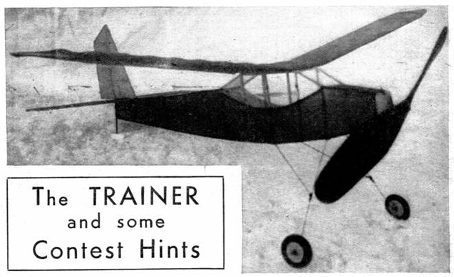
THE TRAINER is the type of model I like to call a utility ship. That is to say, it's a job that can be flown day in and day out, always delivering a pleasing flight and requiring little in the line of maintenance or adjustment. It is this type of model that really teaches model flying.
If you were actually learning to fly, you would spend a great many hours in a training ship ‑ some kind of job with a low landing speed, ample control surfaces, and all‑around ruggedness that would enable the plane to take all the bumps an amateur would be certain to give it. It is the same with models.
All expert model builders were trained with utility models. Their log books would show hundreds of hours of experience flying models of sound design and simple construction. These models flew despite incorrect adjustments inflicted on them by well‑meaning beginners. But gradually the beginners learned to make good adjustments ‑ little tricks hardly visible to the untrained eye ‑ that add many seconds to the flight. Only after you have a full bag of tricks can you get the most out of tricky and temperamental contest models.
The Trainer differs in some respects from other cabin fuselage models given in this department. The rubber motor runs through the fuselage and its attached to the front and rear of the fuselage instead of being mounted too a motor stick. With such an arrangement, the fuselage itself must stand the strain of the wound motor. Naturally, this distorts the fuselage and makes the safety of the model dubious when the rubber is tightly wound. But an 8‑strand motor, as used in the Trainer, will not cause too much trouble. At least it will show you the advantages of using a motor stick!
Another feature of this model, new to AIR TRAILS followers, is the wire landing gear. Its chief claim to glory is its flexibility. We still favor bamboo for landing gears. Let's see what you .think.
CONSTRUCTION
The following materials are used:
8 pcs. balsa 3/32 x 3/32 x 24" for fuselage
1 pc. balsa 1/2 x 1-1/4 x 1-1/2" for nose plug
1 pr, of 1-1/2" celluloid or balsa wheels
4 feet of medium piano wire
1 pc. of tubing about 1/2" length
3 pcs. balsa 1/16 x 1/8 x 24" for wing and elevator
1/32" flat balsa for wing ribs
1/16" flat balsa for tail ribs
1 pc. balsa 1/4 x 1/4 x 30" for leading edge of wing
1 pc. balsa 3/32 x 1/4 x 30" for wing spar
1 pc, balsa 1/16 x 1/8 x 15" for elevator spar
1 balsa block 1 x 1-3/8 x 12" for propeller
1/16" sheet balsa for tail and wing tips
2 large sheers of tissue
14 feet of 1/8" flat rubber
Small bottles of cement and banana oil
1 sheet of cellophaneFour drawings will supply you with details and dimensions. Rather than discuss an itemized building procedure (since modelers are prone to use their own procedure anyway) we'll discuss each drawing, pointing out the features of the Trainer.
DRAWING #1
Here the front half of the fuselage is, shown with top and side views. Drawing #1 is joined to drawing #2 ‑ you can use tracings, if you prefer ‑ to form a complete fuselage layout. The 3/32 x 3/32" balsa fuselage longerons can be pinned directly to the joined drawings or tracings to insure an exact fuselage shape. The curved pats of the fuselage can be bent into the wood by steaming or moistening and pinning in shape while drying.
The front of the fuselage is covered with sheet balsa, since a tissue covering is certain to be punctured during winding.
The nose plug (labeled A) is cut from balsa and should fit into the fuselage. A small piece of hardwood (pine, spruce, bass, etc.) is cemented to the balsa to provide a bearing for the propeller.
The nose plug should fit the nosing snugly. However, when the motor is unwound this plug sometimes falls out and the propeller, dangling at the front of the model, hinders the glide. A rubber band attached to hooks fastened on the top and the bottom of the fuselage will keep the plug in place under all conditions.
The exact‑size wing rib is given in drawing #1. Use this pattern in cutting the 19 wing ribs from 1/32" balsa. Don't neglect to cut away the shaded portions of the ribs, since the spars fit into these notches. The wing is attached to the fuselage by rubber bands slipped onto wire hooks fastened at the front and rear of the wing position.
The position for the landing gear (detailed in drawing #4) is shown. It is cemented and threaded to the bottom of the fuselage at these points.
Notice the section of aluminum tubing inserted in the front of the propeller. A notch is filed in it so the propeller shaft will fall into the notch and revolve the propeller when turning clockwise (from the rear). However, when turning the opposite direction during the glide after the motor is unwound, the shaft will slip over the notch and allow the propeller to free‑wheel with the air stream.
Three copper washers are inserted between the propeller and the nosing to cut down bearing friction.
DRAWING #2
As explained above, drawing #2 is joined to #1 to provide the complete fuselage layout. Notice the sections labeled A‑A and B‑B. This part extends beyond the edge of the drawing, so I had to draw it separately. This is the extreme rear section of the fuselage and should be added to the completed fuselage drawing. In construction, the fuselage is made in one piece.
The rear rubber hook is cemented and threaded to the rear post. Do a good job ‑ it must withstand the pull of an 8‑strand motor. The rear section (from A‑A backward) is left uncovered to help in attaching the rubber motor.
In the top view of the fuselage end section you'll find dotted lines to show the position for the elevator. After it has been built and covered, the elevator is cemented to the top of the fuselage.
A tail skid bent from wire or heated bamboo is cemented to the rear fuselage post.
The shaded sections of the fuselage are covered with cellophane. Recently we discovered a variety that won't wrinkle or shrink when moist. It is a worthwhile improvement, since the shrinking variety will warp a fuselage after it has been on the model for a while. The wrinkle‑free type is lightweight and makes an ideal imitation for cabin windows.
DRAWING #3
The wing is drawn in greatly reduced scale. If you prefer a full‑sized drawing as an aid to good construction, make one on a sheet of paper according to the dimensions given or, better yet, draw it directly on a smooth, flat board. Or paste your paper drawing to the board, if you wish. In this way you'll be able to pin your wing frame directly to the drawing.
The leading edge of the wing is 1/4 x 1/4" balsa, cut and sanded to semicircular shape and butt‑jointed to the tips of the ribs. The spar is 3/32 x 1/4" inserted edgewise into the bottom of the ribs. The trailing edge is 1/16 x 1/8" cut to a triangular cross section and butt-jointed to the rear tips of the ribs.
Sweepback of 1" and dihedral of 2" is given to each half of the wing. These features are an aid to stability and balance. The center section of the wing (1-3/4" wide) is flat, to rest firmly on the top of the fuselage.
The tips of the wing are built up from pieces of 1/16" sheet balsa cemented as shown. This should be a welcome feature for those builders who have trouble making bamboo take the desired shape.
The elevator construction differs from the wing in one respect ‑ the elevator ribs are cut in two pieces and the center spar passes between them. This procedure must be followed since the ribs are not of sufficient depth to permit a spar to be inserted through them. The rib is a streamlined section ‑ that is, the top curve is just the same as the bottom. Cut the ribs to the general shape pictured in drawing #4, in the different lengths required to fit the proportions of the elevator and rudder. Construction of the rudder is identical to that of the elevator.
After construction and covering, cement the rudder to the top center of the elevator as the sketch indicates. The elevator in turn is cemented to the top‑rear of fuselage as described in drawing #2 procedure.
DRAWING #4
The wire landing gear is bent to the dimensions as shown. It is made from three pieces, joined with solder or with thread and cement. Balsa or celluloid wheels are slipped on the landing gear axles. There is another advantage of wire landing gears we've overlooked ‑ the fact that wire axles do not have to be added to the landing struts. Merely bend the ends of the wire struts and slip on the wheels.
The propeller is designed to give plenty of thrust rather than duration. Shape the block as illustrated. The shaded portions are cut away and then the blades are shaped. The propeller shaft is shown in drawing #1.
THE MODEL ready to fly weighed 1.70 ounces. The wing was mounted flat on top of the fuselage ‑‑ no incidence required. Eight strands of 1/8" black rubbers were used as power. The model balanced about 1" forward from the trailing edge of the wing. This was measured at the center of the wing. In altering the balance of your model for best individual flying performance, you must add weight to either the front or rear, since the wing cannot be moved.
No negative thrust was used in the propeller. This might be a valuable addition to your model, however, if it shows a stalling tendency.
The Trainer has a fast flying speed and a good climb. The duration ranged from 40 to 70 seconds, depending on the weather conditions.
Scanned From May, 1936
Air Trails
![]()
![]()
![]()
![]()
[ Home ] [ Previous Plan Pages ] [ Special
Things ] [ Earl Stahl Plans ]