|
|
The MODEL WORKSHOP |
|
The Plan Page
[ Home ] [ Previous Plan Pages ]
[ Special Things ] [ Earl Stahl Plans ]
gt-hunter1@home.com
|
|
The MODEL WORKSHOP |
|

|
Presenting the WAKEFIELD WINNER |
IN presenting this month my 1935 Wakefield Winner, permit me first to give recognition to a high‑stepping,
patriotic cow that had much to do with the winning of the coveted Wakefield Trophy for the United States. Not that "Bossy" helped to build or fly the model, to be sure, but there was a time she held its fate in her hands ‑ or, rather, her hoofs.
It was the day before I packed up my model and shipped it to England. I decided to give the plane one last workout, and after an excellent flight it glided into a pasture in the midst of a herd of cows. No sooner had the ship touched the ground than the inquisitive creatures began giving it a thorough inspection.
Perhaps they wanted to check the wing and tail settings, or discuss the value of the wing section I was using. Anyway, during this procedure I was biding my time at a safe distance, fearful that if I frightened the herd the model would surely be crushed. But when two of the cows, attracted by small American flags pasted to the model, began to lick the fuselage, I lost patience and walked toward them. And that was when Bossy assumed the featured role in our drama. She did not see me until I was within a few feet of her, and when she began a hasty retreat the model was directly in her path.
But Bossy rose to the occasion. Perhaps she, too, wanted to do her part to help the United States regain the Wakefield. Anyway, she hurdled the model, the breeze stirred up by her flying hoofs gently rocking the plane as she scampered away. And thus, through Bossy's indulgence, the model went on to England to become the first plane ever to win the Wakefield Trophy when flown by proxy.
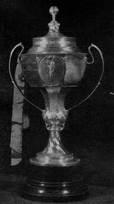
This trophy, which is 26 inches high, is to model airplane building what the Davis Cup is to tennis. Both are fought for internationally ‑ France, Great Britain, and the United States being the principal contenders in both cases. Lord Wakefield, of Hythe, put this cup into competition in 1927, and since then four British and two American model builders have won the trophy.
The 1935 contest was held in England. Lack of funds compelled the six United States entrants to ship their models across the ocean to be flown by English boys since they, themselves, could not afford to make the trip. The 1935 contest was truly international ‑ France, Great Britain, Australia, New Zealand, and the United States each being represented by a team of six.
Simplicity in building and flying is one feature of the 1935 Wakefield ship which will please you. T. H. Ives, the British modeler who flew the model, wrote to me as follows:
"It is simply amazing that a model could be constructed which would weather an Atlantic crossing in a ship's hold and fly straight out of the box, so to speak.
"I was handed the box about 3:30 p. m., and had very little time in which to read your instructions, assemble the bus and test it. However, I found in the first test (with about 100 turns in) that it was in perfect trim. To make sure, I had another flight with about 200 turns and one off the board with 400. Each of these flights showed that no adjustment was necessary, so I left it at that.
"In the competition proper I put in 600 turns for the first flight, as I was confident of a good duration and did not want to strain the motor unduly. To my surprise, this was sufficient to get the model into the region of the thermal currents, and that was the finish, as far as I was concerned. There was little or no wind, and conditions were ideal, with strong sun and only a few clouds. The model soared almost vertically, and we were able to watch it until it finally disappeared in the clouds.
"Fortunately, its observed flight (7 minutes 20 seconds) was of sufficient duration to exceed, in the average, all others."
I might add that the model flew for two hours after passing out of sight of the judges, finally landing on an airport 4 miles away. Under Wakefield rules, a three flight average is recorded. My one flight, divided by three, gave me an average of 2:26.6, which surpassed all other averages of three actual flights.
The accompanying drawings and text will enable you to build a duplicate of this model. The construction follows the same general ideas of construction presented in earlier models of this department. We'll point out the important details of the procedure. So let's go.
FUSELAGE CONSTRUCTION
Material: 10 pcs. balsa 1/8 x 1/8 x 36" for longerons and braces; 1/16 x 1/8 x 7-1/2" pc, of bamboo for nosing (former A); 1/16" sheet balsa for front top of the fuselage; 1/2 ft. of wire for tail skid; 1/2 x 1/2 x 1‑1/2" balsa block for rudder support sockets; 2 pcs. balsa 1/2 x 1/2 x 1‑3/4" for landing‑gear sockets.
First, make a full‑size drawing of the side of the fuselage. The dimensions given in drawing ,#3 will enable you to draw a simple pencil outline, using a yardstick and a sheet of wrapping paper. Cover the drawing with a sheet of wax paper to prevent the cement from "sticking."
The fuselage is built up of 4 balsa pieces 1/8 x 1/8 x 36". First sandpaper these longerons, removing all saw marks, and then soak them in hot water for several minutes. This soaking will make them flexible, so pin them to the drawing, following the outlines you have made. Let the wood dry before attempting to cement the cross struts in position.
The two fuselage sides can be made at the same time ‑one atop the other‑ or separately, if you think you'll be able to do a better job one at a time. Regardless of the procedure, the two halves must be identical.
Drawing #3 will show the width of the fuselage at the various positions. In every case, the strut is simply butt‑jointed to the longerons. To speed up the work, you can pin the struts in position until dry and then remove the pins.
Fuselage construction at the front of the fuselage (A, B, and C) is different from the rear. Drawing #4 will clear up this feature. Notice also that the exact shape and size of the fuselage at points A, B, and C is given in drawing #1. This part of the fuselage is covered with 1/32" sheet balsa as an aid in maintaining the curve of the nosing and strengthening the fuselage to take up the shock of the landing gear.
Since the size of the shipping case had to be kept small, the original Wakefield ship was made with a demountable rudder. With a demountable rudder, landing gear, elevator, wing, and propeller, the model fits snugly into a 6 x 8 x 4l" box. This is in sharp contrast to many model boxes.
The rear tip of the fuselage is a balsa tube. This is easily made by pushing a pointed piece of bamboo (1/8 x 1/16") lengthwise through a balsa block 1/2 x 1/2 x 1-1/2". After you've reamed out the hole, cut away the excess balsa until the walls of the tube are about 1/16" thick. To prevent the tube from splitting, wrap it with thread and coat with cement. Next attach it to the four fuselage longerons as illustrated in drawing #4.
After the fuselage is assembled, round the edges of the longerons. Sand off the sharp edges, but don't weaken the fuselage by excessive sanding at any point. Any blotches of cement that will mar the appearance of the covered fuselage should also be sanded off.
LANDING GEAR
Single bamboo‑strut landing gear is used. The bamboo is sanded oval from a 3/32 x 3/16 x 9‑1/2" piece. The struts fit into balsa sockets prepared like the one attached to the rear of the fuselage. (See fuselage construction.)
These balsa sockets are fastened to former B as indicated in drawing .#1. Cement alone will not hold them in position, so wrap the joint with thread. If the landing struts become loose, thicken them slightly by coating the ends with cement or banana oil. However, do not insert them into the sockets until they've dried. If you do, you'll no longer have a demountable landing gear, since the struts will be permanently fastened.
The wheels and their attachment are shown in drawing #3.
A wire tail skid is fastened to the bottom of the fuselage at K. The skid is about 1-1/2" high and should hold the empennage (elevator and rudder) a safe distance off the ground to prevent damage.
MOTOR STICK
At every contest I have a hearty chuckle at the discomfiture of the model builders who haven't yet learned that using a demountable motor stick is infinitely better than winding the rubber motor through the fuselage. A scene common at any contest is one of a perspiring modeler busily turning a creaky winder. Gradually the rubber becomes tighter. The builder carefully examines it and then mutters something about adding a few more turns. No sooner has he begun to do this than the motor snaps and the pieces go tearing through the fuselage. Usually the rubber carries the side of the fuselage along with it and another model is eliminated from the contest.
This is where the modelers who use motor sticks have the laugh on their unfortunate brothers. If they break the rubber while winding, they merely get a new motor and start winding again ‑ much easier than building an entire new fuselage! With a motor stick you can always wind your motor to the limit with no danger. This will assure you maximum duration. If you don't use a demountable stick, you take the model's life into your hands every time you wind the motor.
The motor stick, illustrated in drawing #5, is built up of a U‑beam covered with a top strip. The dimensions of the stick are 9/16 x 3/8 x 26‑5/8". The walls of the stick are 3/32", A square bulkhead or partition of 1/16" sheet balsa is cemented inside the stick every two inches. These bulkheads hold the walls of the stick rigid and give the stick added strength.
The 3/32" top strip is fastened to the stick with cement. Apply the cement in 2‑ or 3‑inch lengths, using rubber bands to hold the cemented portion in place while you go on to the next section.
In drawing #5 you'll notice that plugs of solid balsa are inserted into the front and rear ends of the motor stick. The reason this is done is to make a solid foundation for cementing the front nosing and the rear hook. The front nosing is a 5/8" balsa block, cut to fit former A, and shaped as shown.
MOUNTING THE MOTOR STICK
The stick is fastened inside the fuselage at two points ‑formers A and I. The support at A, shown exact size in drawing #1, is built up of three thicknesses, of 1/32" sheet balsa. It is cemented inside the bamboo ring. The clip‑support at former I, shown in drawing #3, is bent from wire. When the stick is resting in the clips, the top should be parallel to the top of the fuselage between formers D and F.
The balsa nose piece cemented to the front end of the stick should be fitted in place while the stick is inside the fuselage. The nosing should fit snugly against the front of the fuselage. Cut a notch in the bottom of the nosing and cement it to the stick.
A clothing snap fitted to the inside of the nosing holds the motor stick in place. Half of the snap is cemented to the top inside of the nosing, the other half being cemented on former A. Since these pieces must stand a great deal of strain, strengthen the cement with thread or else insert a bent pin through the clothing snap into the balsa, thus "tacking" the snap to the balsa. When removing the stick from the fuselage, insert the tip of a knife between the balsa nosing and former A to separate the clothing snap.
As shown in drawing #5, punched snaps serve as bearings for the propeller shaft. One is cemented to the outside and one to the inside of the balsa nose block. Notice that the one on the inside is cemented 1/2" above the stick, or 1/16" higher than the one on the front of the nosing. This adds negative thrust to the propeller ‑ a feature which helps keep stalls out of the model under full winds.
WING CONSTRUCTION
Material: 18 ribs cut from 1/16° balsa, using the pattern in drawing #1; 4 balsa spars 1/8 x 1/4 x 24"; 2 balsa leading edges 1/8 x 1/8 x 24"; 2 balsa trailing edges 1/8 x 1/16 x 24"; 2 bamboo wing tips 1/16 x 1/16 x 8"; a small piece of wire for wing hooks.
Make a metal template of the main wing rib by pasting the rib shape (drawing #1) on a piece of metal and cutting the metal to exact shape. Use this template to cut out 18 ribs from 1/16" sheet balsa. Be sure to cut the notches for the leading edge and the two spar holes.
Each half of the wing is made separately. Mark the rib positions on the spars, using a soft pencil lightly so as not to damage the wood. See drawing #2. An indelible pencil or a piece of crayon is also useful for marking balsa. Slip the ribs onto the spars, adding a touch of cement to hold them in position. Next pin the wing to a flat surface. The leading edge is 1/8 x 1/8" balsa inserted cornerwise into the front of the ribs. The outer corner is sanded to a circular shape so it rounds out the curve of the wing. The trailing edge is of triangular shape, cemented to the rear tips of each rib. Both the leading and trailing edges should be carefully cut to shape and fit before cementing to the ribs.
The wing tips are bamboo 1/16 x 1/16". The two spars are tapered to 1/16" at the tips where they join the bamboo tips. The bamboo can be shaped by wrapping it around a heated tin can, around a hot soldering iron, over a candle flame, by steaming ‑ to mention just a few of the methods used by modelers.
JOINING THE WING HALVES
In drawing #5, the four pieces A, B, C, and D form the center section. These pieces are the same size as the spars, leading, and trailing edges. They are butt‑jointed to the wing halves. Use cement in making the joint. It will provide plenty of strength, if you apply it liberally and allow time to dry thoroughly.
Notice, in drawing #2, that the tips of the wing are raised 3-1/2" above the center section. This dihedral can be obtained by cutting the ends of pieces A, B, C, and D to the proper slant before cementing them to the wings. Be sure the opposite ends have equal degrees of slant.
Wire hooks, shaped as shown in drawing #1, for attaching the wing to the fuselage are cemented to the two center ribs. See drawing #5. The hooks are cemented to the top of the wing rather than have them extend down alongside the fuselage. With them on top, the wing can shift from side to side without having the attaching hooks tear through the fuselage. This is what inevitably happens when the wing of the model strikes an obstacle while in flight.
ELEVATOR AND RUDDER
Material: 11 elevator ribs of 1/16" balsa, 5 rudder ribs of 1/16" balsa (both rib patterns are given in drawing # 1) ; 3 pcs. balsa 1/16 x 1/4 x 24” for spars; 2 pcs. balsa 3/32 x 3/32 x 24" for leading edges; 2 pcs. balsa 3/32 x 5/16 x 24" for trailing edges; 3 pcs. bamboo 1/16 x 1/16 x 7" for wing tips.
Elevator and rudder construction is the same as in the wing ‑ that is, the two main spars run through the ribs instead of being inserted from the top and bottom. You can see from drawing #2 that the rudder is about 1/2 the size of the elevator. No dihedral angle is put in the elevator. After every construction step, pin the framework to a flat surface so it dries without warping.
ATTACHING ELEVATOR
A wire hook mounted to the leading edge of the elevator fits onto the fuselage at K, as shown in drawing #4. This wire hook is shown exact size in drawing #1. A small block of 1/16" balsa is cemented to the bottom of the leading edge. This block sets the elevator at the correct angle of incidence - about 2 degrees. In making this setting, it is assumed that the top of the fuselage between K and L is perfectly flat, parallel to the line of thrust. The elevator is fastened only at the leading edge. The pressure of the rudder will prevent the rear of the elevator from moving.
ATTACHING THE RUDDER
A bamboo spar 1/16 x 1/8 x 5-1/2" is inserted through the rudder. It is labeled X in drawing #4. This spar is parallel to the rear rudder spar and spaced 1/8" to the front. It fits into the balsa socket at the rear of the fuselage. When it is in place, the rear of the rudder should fit snugly against the rear of the fuselage.
Let's check this procedure again. The bamboo spar doesn't run the entire length of the rudder, but through three rudder ribs. It is attached the same way as the balsa spars. Bamboo is used to take up the shock of bending and twisting which the rudder naturally encounters. The space between the bamboo spar and the rear balsa spar should be just a trifle greater than the thickness of the rear‑fuselage balsa tube described under fuselage construction. The rudder is kept in the "socket" by tying the bottom tip of the rudder to the bottom of the fuselage, with rubber bands. Hooks for this purpose, shown in drawing #1, are cemented as in drawing #4.
The front of the rudder is secured in much the same way. The wire attached to the fuselage is shown in drawing #1. It is cemented to the top of the fuselage about 1/2" in front of K. This type of fitting permits an adjustment of the rudder by sliding the rubber back or forth across the fitting. By tightening the rubber hands, the rudder can be made rigid; yet it can be "torn down" in a second or so for packing.
PROPELLER CARVING
Material: 1 medium lard balsa block 1‑1/2 x 1‑5/8 x 16‑1/2"; brass tubing (1/16" inside diameter) 1-1/2" in length; a small piece of silk for re-enforcing the propeller.
The propeller block is tapered at the tips and at the center as shown in drawing #6. This work should be done carefully. Be sure to mark off the block accurately with pencil and ruler before cutting. A small jig saw can be used in shaping the block. A hole is punched through the center of the block. Make sure it passes through tile exact center.
In cutting the blades use a sharp knife. The propeller tapers from 1/4" at the center to about 1/16" at the tips. About 1/8" camber is sanded in the rear of the blades. After the blades have been cut to equal thickness, use the full size blade pattern in drawing #1. Lay out the exact blade shape. Now give the propeller a final once‑over ‑ cutting away the thick spots and sanding out the rough spots. Balance it by inserting a needle through the center hole and resting the needle on your finger tips. When the propeller rests in a horizontal position without swinging either way, the balance is good enough for our purposes.
FREE‑WHEELING
At the St. Louis contest last year, Frank Zaic, a well‑known modeler, showed us a new type of free‑wheeling. It is especially well adapted to many ‑ strand motors. Frank learned about this device from Louis Gerami, a Brooklyn model builder whose ingenuity is responsible for this clever method of free-wheeling. I incorporated this method into my Wakefield model, which took form shortly after the St. Louis contest. It worked perfectly. It never "let go" under full power and never failed to free‑wheel. Thanks to Louis Gerami, we have a reliable free‑wheeling for our model.
Drawing #6 illustrates the Gerami free‑wheeling. A section of brass tubing is inserted through the center of the propeller. A piece of wire is soldered to the tubing and the ends bent so they penetrate into the propeller. This acts as a sort of "anchor" and prevents the tubing from working loose. The tubing and the wire prongs are carefully cemented in position.
The wire catch that engages the propeller shaft when the motor is turning is pivoted in a short section of brass tubing. A wire reinforcement is soldered to this section. Notice that the wire "catch" is slipped through the tubing before it is cemented in place on the propeller. Cement a patch of silk to the propeller where the "catch" presses. If the cement you are using has dubious "sticking" qualities, use strips of silk to help secure the brass tubing.
COVERING
The model was covered with a grade of tissue known as "superfine," which can be procured from model shops. However, be sure you specify it for outdoor models. Use banana oil to fasten the tissue. The tissue grain runs lengthwise on the wing and fuselage. Spray the tissue with water, using an ordinary insecticide spray gun. Give the tissue a uniform soaking. Be careful when you handle the water‑soaked tissue, as it is easily torn. To prevent the wing and elevator from warping, as they dry, pin them to a flat surface immediately after spraying.
The tissue is treated with a coat of banana oil. This will waterproof it and make the wing and tail surfaces rigid.
The original model was covered with white tissue and decorated in black. This is the simplest combination, since black india ink can be easily used in a draftsman's pen and compass. However, a white model will not remain in sight as long as a red model.
FLYING
The balancing point of the model is indicated by the specifications given at the end of the article. If you've followed the plans, your model will balance near the same point. You can move the wing to compensate for any variation in weights. Gliding the model is a check on its balance. My model glided 50 to 60 feet when launched from shoulder height. A flat glide is important, so develop this quality in your model.
If your model gives you trouble by stalling or diving, first of all check the wing and elevator settings ‑ 5/32" block under the leading edge of the wing and 1/16" block under the leading edge of the elevator.
You should be able to remedy stalls and dives by moving the wing forward or backward. Remember: if the model stalls, move the wing toward the tail, and vice versa for dives.
Under full power the model climbed very steeply in a tight left turn. As the power diminished the turn became wider, finally ending in a right circle during the glide. The rudder was set in a neutral position. The trailing edge of the left wing was warped down a trifle to compensate for the torque of the propeller.
SPECIFICATIONS
| Wing area | 197 sq. inches |
| Elevator area | 64 sq. inches |
| Rudder area | 30 sq. inches |
| Propeller area | 28 sq. inches |
| Propeller pitch | 24 inches |
Settings
| Center of gravity location: | 2-1/16" below the wing 11/16" above thrust line 2‑3/4" to 3-1/4" back of leading edge of wing. |
| Main wing setting | 2-3/4 degrees positive |
| Elevator setting | 2‑3/4 degree positive |
| Propeller thrust | 4 degrees Negative |
WEIGHTS
| Wing | .710 ounces |
| Elevator | .290 ounces |
| Rudder | .140 ounces |
| Propeller | .260 ounces |
| Rubber | 1.200 ounces |
| Stick | .475 ounces |
| Wheels | .255 ounces |
| Fuselage | .740 ounces |
| Total R.T.F. | 4.070 ounces |
Scanned From April 1936
Air Trails
![]()
![]()
![]()
![]()
![]()
![]()
[ Home ] [ Previous Plan Pages ] [ Special
Things ] [ Earl Stahl Plans ]