The Plan Page
[ Home ] [ Previous Plan Pages ]
[ Special Things ] [ Earl Stahl Plans ]
gt-hunter1@home.com
BUILDING THE VULTEE VALIANT
A realistic model of the famous U. S. Army trainer, that is
easily built
by SYDNEY STRUHL
|
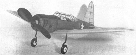
The completed model with efficient propeller is a
fine flier |
|
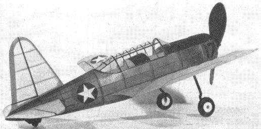
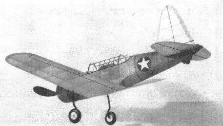
With "greenhouse," single strut landing gear and
decorations it looks just like the full scale plane |
|
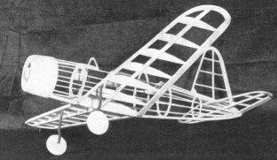
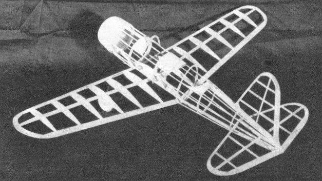
Construction is simple, but light and strong, made up
of comparatively few parts |
LATEST
in the series of Vultee basic trainers used by the
United States Army Air Corps which began auspiciously with the BT-13, the
Valiant now serves as the BT-13A or LT-15, depending on engine installation.
Powered by either Pratt & Whitney or Wright radial engine developing 450 hp.,
the Valiant has a top speed of 182 mph. and a service ceiling of 21,000 feet. It
has a wingspan of 42 ft., is 28 ft., 7 in. long, and measures 9 ft., 1 in. in
overall height.
This fine training plane, designed expressly for the
U.S.A.A.F., is the backbone of our Air Cadets' basic flight training;
practically every one of our boys who sprouts wings on his tunic soloed in this
plane. The Valiant is ideally suited for rough training routines. Being
extremely rugged and stable, Cadets with "air sense" find little difficulty in
learning to fly and solo in one of these ships even with 450 hp. mounted in the
nose.
Incidentally, the author got a rather odd "kick" out of
modeling this basic trainer, for being an Aviation Cadet in Uncle Sam's Enlisted
Reserve, lie expects to be sitting in the cockpit of a BT-15 very shortly.
The model has been accurately reproduced and is worthy of any
effort expended on its construction. It is not only attractive as a display
model but is also a speedy, stable flier. Because of its excellent proportions
it is ideal for scale endurance meets.
The model Valiant is simply constructed in the conventional
manner. While the test ship was built of half balsa and half pine, the plans
call for all balsa which is of course the best material. However it is readily
adaptable to construction using slightly heavier white pine and basswood now
being sold at most model shops. All wood should be selected carefully to assure
the lightest, strongest structure possible. In the process of assembly all
frames should be made with accuracy and each joint cemented firmly.
FUSELAGE:
Begin construction by making the keel pieces. Trace top and
bottom outlines of the side view to get the correct shape; the bottom keel is a
continuous piece extending from nose to tail, and the top keel is two separate
pieces. Average depth of the keels is about 3/16"; they are cut from 1/8" sheet
balsa. Bulkheads are shown full size on the plan and they are cut from 1/16"
sheet except bulkheads A and B which are 1/8" sheet balsa. Two of each are
required. You will notice that the bulkheads are marked where the stringers run;
they are notched during the actual construction to insure accuracy. Cut the keel
notches however and merely mark the other positions.
Pin the keel pieces into position over the plan and begin
actual fuselage assembly. Temporarily cement a piece of 1/8" x 3/16" balsa
between the top keels to join them at the opening created by the cockpit. Cement
half the bulkheads to their respective positions and when dry remove from the
plan and attach the remaining ones to the other side. Align the bulkheads
accurately so they are exactly perpendicular to the keels. Cut notches in the
bulkheads and insert the 1/16" sq. stringer along the thrust line, being careful
not to pull the fuselage out of line. Place the remaining stringers, cutting the
notches as required with a sliver of a razor blade. Once a stringer is attached
to one side, always place another in the corresponding position of the other
side. After the stringers are all attached, the temporary brace at the cockpit
is inserted.
The engine cowl is made of 1/16" sheet cemented between
bulkheads A and B. Note that the sheet is laid on top of the stringers to cause
a slight rise. Make a paper pattern of the cockpit shape and cut the 1/32" sheet
balsa to the required shape. Pins and rubber bands will keep the sheeting in
place until cement is dry. Cover the section behind bulkhead D with 1/32" sheet
to form the turtleback.
The cowl front is made from three discs of 1/8" sheet balsa
which are cemented cross-grain. The discs have the centers removed to the extent
indicated on the plans. Attach the unit to the first bulkhead A and when dry
roughly cut to shape. Finish by carefully sandpapering the cowl and discs to
required shape. The nose plug is hardwood. The removable nose plug is made to
fit snugly into bulkhead A.
TAIL SURFACES:
Construction of the tail surfaces is easy. Both the
stabilizer and rudder are built in a similar manner. To obtain greater strength
the stabilizer is built in one piece. All sizes are given in the plans. The tips
are soft 1/8" sheet balsa. When dry the frames are removed from the plans. Trim
the trailing edges and tips to a streamline shape, using a razor and sandpaper
for this work. Check the rudder and stabilizer for warps. If you can, remove
with steam. If it is necessary to use wood other than balsa for the stabilizer
and rudder, it must be remembered that they be light but still strong. To
accomplish this reduce the size of the various parts.
WING:
The wing is easiest assembled in one piece; the builder will
have to make a left side plan as there was insufficient room for it on the
drawing. Ribs are cut from 1/16" sheet balsa and two of each is needed except
No. 1. Sand them. carefully to the exact size and cut notches for the spar. Spar
is cut from 1/16" sheet balsa as shown by the dotted lines. Leading edge is 1/8"
x 1/4", trailing edge is 1/8" x 3/8" tapered stock. Tips are cut from 1/8" sheet
and assembled over the plans. With pins hold the various parts in place over the
plan until the cement has set. When dry, crack the spar and edges and install
the required dihedral; recement the dihedral joints firmly. Finally trim and
sand the leading and trailing edges and tips to conform with the airfoil shape.
To keep weight down to a minimum the builder using heavier
wood will have to use material of smaller crossection, particularly the leading
and trailing edges. Ribs should be cut from the thinnest stock and lightening
holes at points of little stress will tend to reduce the weight of heavier
material.
A landing gear of the type used on the Valiant always
presents a problem to the model maker. However, the landing gear developed for
this model is easy to make, accurate in appearance and strong enough to take all
the abuse the model can give. .040 steel wire is used and the top is bent in
such a manner as to join the wing spar and rib No. 3. Make a right and left
strut. With thread bind the struts to the spar and then use needle and sew right
through rib No. 3, and about the wire. Apply several coats of cement to the
thread wrappings and adjacent areas. The rubber tubing covers are not slipped on
until the wing has been covered.
Wheels may be purchased or they can be made from laminations
of 3 1/8" sheet discs. Cement washers to both sides of each wheel so they will
turn freely and accurately.
PROPELLER:
Select a very hard balsa or soft pine block of the correct
size for the propeller. Drill the tiny hole for the prop shaft and then cut out
the blank as shown. A right-handed propeller is to be carved. Cut away the back
face of the blank first until the backs are as desired, then cut away the front
until blades are of proper thickness. Reduce the depth of the hub and shape the
blades in a manner similar to the prop shown in the photos. With rough and then
fine paper sand the propeller to a smooth finish. It is wise to install some
type of free-wheel on the prop. Apply several coats of clear dope with light
sanding between each to smooth and harden the surface.
The nose plug is purchased or made from hardwood such as
pine, etc. Fix the line of thrust by cementing washers to the front and back of
the plug.
.040 music wire is used for the propeller shaft. A loop to
which a mechanical winder can be hooked should be bent on the front of the
shaft. Place several washers between the propeller and nose plug to reduce
friction.
COVERING AND ASSEMBLY:
First step in preparing for covering is to work over
the entire structure with fine sandpaper for a neat covering job. Regular
colored tissues or Silkspan is used, banana oil or thin dope is the adhesive.
Use individual sections of tissue for each flat section of each side of the
wing, tips, tail surfaces, etc. In covering the fuselage it will be necessary to
use numerous small pieces to work around the curves without wrinkles; the tissue
must be lapped carefully to assure a neat covering. Lightly spray the covered
parts with water to tighten the tissue. The flying surfaces must be supported
level while drying so they will not warp.
Following is the recommended procedure for assembling the
Valiant: Cement the wing to the position indicated on the plan; if the structure
has been reproduced accurately, the angle of incidence will automatically be
correct. The 1/32" sheet fillet pieces are shown on the plan. This pattern
indicates the shape of the fillets on the original model but most models will
vary somewhat, so paper patterns should be made to fit your model exactly before
the sheet balsa ones are cut. Once the fillets are cemented to position, the
several small openings at the junction of the wing and body should be filled in
with scraps of soft 1/16" sheet balsa. Sand smooth and cover the fillets with
colored tissue.
To set the stabilizer in position it will be necessary to
temporarily cut the keel in the rear. Cement the stabilizer at a slight degree
of negative angle. The rudder is attached exactly perpendicular to the
stabilizer and it is offset 1/16" to counteract torque. Small tissue fillets at
the tail surfaces will enhance the model's appearance. Moisten any wrinkles and
permit to dry before applying a coat of clear dope to the entire model.
Addition of various minor details completes the construction.
The cockpit enclosure is made from thin sheet celluloid. Make accurate patterns
before cutting the celluloid; avoid cement smears when cementing in place. Slip
the rubber tubing on the wire struts. Wheels are held to the axles by washers
soldered to place. Control surface outlines are black tissue strips doped to the
covering. The cowl front and top of the fuselage anti-glare is painted black.
The insignia used on the original model was purchased. A tail wheel and other
details found on photos of the real ship can be incorporated to make your Vultee
more attractive.
FLYING:
Our original test model is powered with six strands (three
loops) of 3/16" flat brown rubber. It is best to lubricate the motor before
placing it within the fuselage. Hook the strands to the prop shaft and then drop
the other ends through the fuselage. It may be necessary to remove a small
portion of the covering in the rear in order to get the strands into the
position to be held by the removable bamboo pin.
Make first flights over soft grass but if none is available,
make first tests R.O.G. with but a few turns in the motor. In all probability
the model will be out of balance so a small corrective weight may be needed. As
correct balance and stability are attained increase the number of turns.
Offsetting the thrust line will aid in controlling the amount of circle in
either direction, and by tilting the thrust line down a tendency to stall can be
eliminated. For maximum performance stretch the rubber motor and wind with a
mechanical winder. Keep 'em flying l
VICTORY
Scanned From June, 1943
Model Airplane News


[ Home ] [ Previous Plan Pages ] [ Special
Things ] [ Earl Stahl Plans ]