The Plan Page
[ Home ] [ Previous Plan Pages ]
[ Special Things ] [ Earl Stahl Plans ]
gt-hunter1@home.com
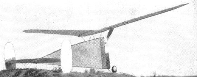
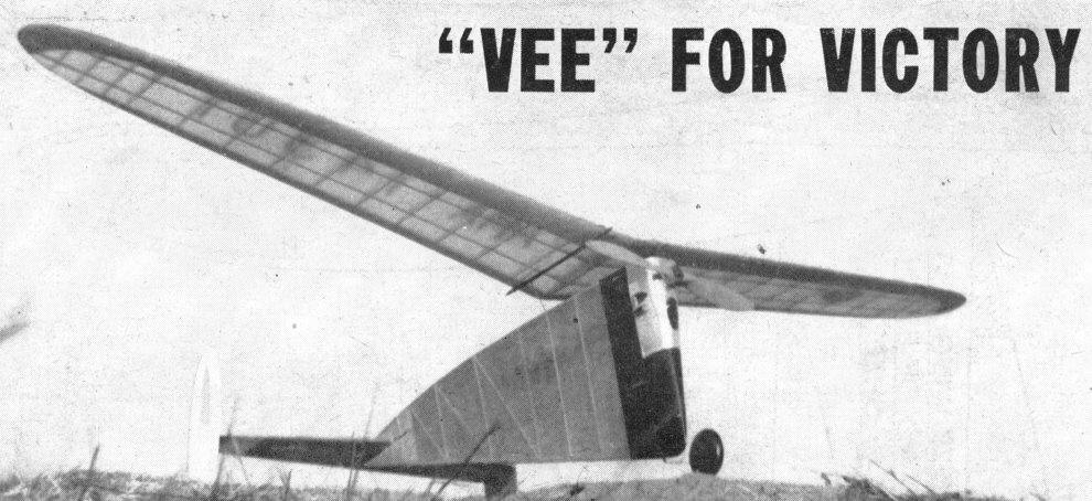
The high aspect ratio soaring gas job, stable in any wind
How to build this completely stable high-performance gas model
by RALPH J. ULLENBERG
|
Much merit for the "Vee's" success must be saddled on Mr. Charles Grant. I would like to spare Mr. Grant his modest blushes, but honor compels me to mention that the design is based largely on his series of design articles presented in both M.A.N. and his book, "Model Airplane Design and Theory of Flight". Recognition is also due to Mr. Edward Pietrzak for his practical advice Mr. James Gilchrist for his fine job of constructing an extra model for experimental purposes and Mr. Edward Krause for his inspiring encouragement. |
|
A deep body makes it stable in all kinds of weather |
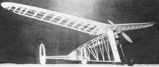
Structure is simple and all parts are easily demounted |
|
It is light in weight, weighing only 8 oz. per square foot |
|
TEST flying a model is usually a trying experience for its builder . . . He realizes a crisis is at hand . . . His nerves are tense . . . His imagination stirs . . . Before every flight he alternately sees visions of the new model executing unequaled performance or striking the sod with destructive violence.
Test flying the "Vee," however, was a refreshing relief. Its very first flight was almost perfect; adjustments were unnecessary. Stability was by no means a stranger and subsequent flights proved the craft faithfully consistent and absurdly easy to fly.
The high aspect ratio wing may be viewed somewhat askance by those advocates of the short stubby variety. Nevertheless its use was justified. The rate of climb was perceptibly increased, and the long slithering glide revealed a decided tendency to alienate "ole mama" earth. Even if you are not planning on building another gas model at present, the wing may prove especially adaptable to that new soaring glider design you have in mind.
Two of these models have already been built, and two slightly modified versions, of Class A and B distinction, were also built and flown with sparkling performance.
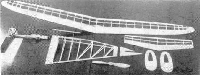
Balsa construction is used throughout. If you happen to be possessed of only a limited stock it is suggested that basswood could be incorporated wherever you deem it advisable. Use your discrimination in this. Strive to blend proper strength with reasonable weight.
After enlarging the drawings to workable size, a protective covering of waxed paper over them would not be out of place.
Constructing both sides of the fuselage at the same time, one atop the other, will prove most accurate and convenient. Needless to say, extra coatings of glue at vital joints would be very good modeling sense. Lower longerons of the completed sides are now cemented together, and upper cross braces added between the top longerons. A 1/8" x 3/8" cap strip is cemented to the bottom of the lower longerons and the edges rounded. Inlay the framework with sheet wherever indicated. The fuselage, at this point, would thank you for a neat job of sanding, so be a sport and kindly oblige.
You will note the model features a demountable tail piece: shock, frequently incurred at this point, will then be appreciably reduced. Most important however is the fact that the builder can easily adjust his stabilizer setting, if necessary, by merely inserting slivers of wood between the tail piece and fuselage proper.
A slot will have to be cut out at the rear of the tail piece to receive the stabilizer. This is very exacting work. For appearance's sake the slot must fit neatly around the stabilizer. To dispense with any flight testing difficulties the builder would be wise to make absolutely certain the stabilizer incidence conforms exactly to the amount on the drawing. The same, of course, holds with the wing.
Landing gear is bent to shape and mounted to the front of the firewall as shown in Plate 1. The nose block and plug are then cemented to their indicated locations and the whole unit given five coats of heavy dope.
A radiantly mounted Forster 29 engine is used on the original. The air intake tube extends through the firewall into the fuselage. Access to the tank and carburetor assembly is gained through the trap door on top of the fuselage. The fuel drain, located below the tank, disposes of any fuel accidentally spilled into the fuselage while fueling. You will, of necessity, have to mount your engine inverted to obtain the low center of gravity position shown on Plate 1. It will also improve appearance and lessen drag.
A motor cowling is easily made of sheet aluminum; if unavailable, asbestos, fiber or some similar substance can be substituted. A cooling vent is cut in front and two smaller ones on each side. A study of the pictures will give you a good idea. Cowling is held on with pins stuck into the nose block and into the 3/16" sheet balsa former located at the top of the firewall above the engine.
Empennage construction is fully explained in Plate 1. Sand the fins to a streamlined crossection, and cement them well to each end rib in the position shown. It is vital that the stabilizer tip ribs be perfectly parallel to avoid any possibility of fins working against each other while in flight. Check this with a ruler.
The wing is made in two halves. Start off by first cutting out all wing ribs very accurately. They are then cemented at their relative positions to the 1/16" x 1/8" spars. Incline the butt ribs at a slight angle to allow for proper dihedral when both wing panels are later joined together. Trailing edge is appended next, making sure it is cut to the correct taper. The leading edge is cemented on last, so unpin the wing from your workbench and apply the 1/16" sheet balsa leading edge covering. This is done in the following manner:
First warp the sheet covering to the curve of the ribs by soaking it in hot water and holding it in position with pins and rubber bands. Be sure to leave about 1/4" extend past the front of the wing. Then, after the sheet has dried, it will have assumed the shape of that part of the airfoil curve to which it shall be attached. Glue the sheet covering to the ribs, and sand off the excess material, extending past the fore part of the wing, flush with the front of the ribs. Now all that remains is to add on the 3/16" x 1/2" leading edge and trim and sand it to the airfoil contour.
After both wing halves are made cement them together, and raise the tips to the required dihedral angle. Finish by smoothly sanding the whole assemblage.
Before starting to cover your model it would be very well advised to go over it again, check and eradicate any rough spots on the framework. The original "Vee" flaunts red gas model Silkspan on fuselage and stabilizer. The wing and fins use superfine tissue. Miscellaneous parts are trimmed with black dope. Cover in the usual manner and apply enough dope to gas and water-proof the model, especially in the vicinity of the fuel drain. Sand lightly with fine sandpaper in between coats.
The firewall and tail piece are held on with hooks and rubber bands. Strap the wing to the wing mount with rubber, and your "Vee" is finished.
Before trying a flight we would do well to check our model. The wing leading edge must be 13/32" higher than the trailing edge to provide positive 3 degrees incidence. The stabilizer is set at negative 2 degrees incidence; in this case the leading edge will have to be 3/16" lower than the trailing edge. These measurements are taken at the butt chords of both wing and stabilizer. Center of gravity location and alignment are checked next. The model is now in condition to function satisfactorily.
A calm day will, of course, greatly benefit your test flying -- wait for one. A few test glides in tall grass should be made before attempting anything more daring. Proper balance is secured by shifting the wing back or forth until the model is gliding with flatness and stability. Confine incidence adjustments, if necessary, to the stabilizer alone. For your first powered flight fly the model under low throttle with a few seconds motor run. Observe the flight carefully, taking note of the model's peculiarities. It should circle to the left in a steady radius. If preliminary testing looks promising open up the motor by degrees, during subsequent flights, until full power is reached. If any need for adjustment arises regulate it accordingly. If built as presented, there is little doubt your model will be flying consistently with a readiness that is downright courteous.
VICTORY
Scanned From June, 1943
Model Airplane News
![]()
![]()
![]()
![]()
[ Home ] [ Previous Plan Pages ] [ Special
Things ] [ Earl Stahl Plans ]