|
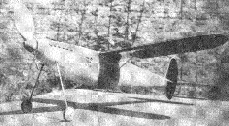
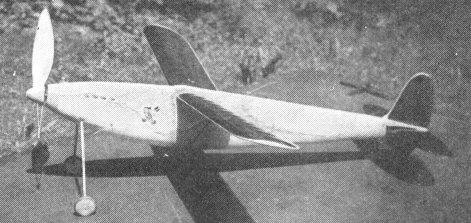
Monocoque body and single blade prop give strength and efficiency |
It slides through the air with the greatest of ease |
|
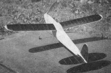
A high aspect ratio provides soaring efficiency |
|
The Plan Page
[ Home ] [ Previous Plan Pages ]
[ Special Things ] [ Earl Stahl Plans ]
gt-hunter1@home.com
A Super Streamline Wakefield Model
How You Can Build a Consistently Flying Model That Has Placed in Nearly Every European Contest
By ALFRED VanWYMERSCH
|
Monocoque body and single blade prop give strength and efficiency |
It slides through the air with the greatest of ease |
|
A high aspect ratio provides soaring efficiency |
|
THE MODEL we present here is our fourth development of monocoque contest models. The first two had bodies hollowed out of a block of balsa. As this was definitely too heavy we resigned ourself to planking the fuselages, and immediately found this much less difficult than we had imagined it would be. This model flew and still flies well, but was a bit tail heavy.
This last model is therefore an improved version, also having the nose lengthened about two inches. That we now have the right proportions is proven by three other models which were found to be in perfect balance. Of course it is necessary to observe carefully the weights given on the plan.
The plane has consistently made long flights and still after a year's flying, it will turn in average flights of three and a half minutes in calm non-thermal weather.
Its official flights in some contests were: April '38: Gand 4'8" (Belgian record at that time). May '38: Namur 4'55". June '38: Fourth at international contest in Paris. July '38: Tirlemont. Won with two flights 3'21" and 3'27". 31st of July '38: Wakefield Cup at Paris. 10th place; first on Belgian team. Aug. '38: Coupe du Roi or King's Cup (international) 3rd place with 7'24", 3'6", 3'23".
The Wakefield contest held a lesson all its own which is worth telling. Following our usual practice, the plane exceeded minimum weight by a third of an ounce. However it was a very recent edition so it happened that the terrific heat during the day preceding the competition completely modified the weight, settings and balance. In fact the plane just barely had the required weight when it was weighed in. On the first flight, after a spectacular climb the nose block fell out somehow. This seeming cause for the following series of stalls only served to hide that the plane was deregulated, and it was only after the second flight that we woke up and corrected the settings. It then made a flight approaching five minutes. The moral of the story is: It does no harm to try out the plane before the contest.
A word about the power used, because some of you fellows will think it is exaggerately low. The fact is that the motor gives ample power between the 3rd and 9th wind up. After that there is not enough snap left for contest flying when using this power ratio. However by using the rubber in this way we have a greater power-weight ratio, since if we use a well broken-in motor, at least 28 strands is used; which makes one-sixth more weight of rubber. Of course it cannot be called economical. We firmly believe, under such conditions, in changing the motor for each flight, thereby making regular flights and also giving the other motors a chance to "come back." In this manner a set of three motors can be used during two contests.
With this power we get as much and more height as your American models but it takes 20-30 seconds longer to get there. On the other hand power lasts at least one to five minutes, which is almost 60 seconds more than your high-powered jobs last. It is also a fact that streamlined jobs do with less power.
This automatic "down-thrust" also helps a great deal since, without it, we had to use quite a bit of so-called "downthrust" (see Mr. Mac Lean, page 15, Feb. '39) on account of the burst of power when wound up full. However at anything under the maximum power the ship flew better (more efficiently) without "down-thrust." In other words, the "down-thrust" was just a parasite load on the nose of the plane after the first five seconds motor run. The gadget we use makes for a more continuous and longer climb in practice.
One last word before giving the construction. Our 1939 model will differ only in small details and notably in that it will use a folding prop.
Wings. The builder must first redraw the wings full-size on ordinary paper. Don't forget to draw one left and one right wing. The original wing ribs were cut on a bandsaw and were hollow. This was not done to gain a bit of weight but rather for ease of assembly, to permit the spars to be placed inside the wing in such a manner that they do not touch the covering, thereby producing a more perfect covering job. Also this permitted an easier use of bisemmetrical spars or rather of tapered section. The usual strongly cambered wing has a tendency to curl upwards on account of the tension of the covering. To avoid this raise the center line of resistance of the spars by putting more strength at the top of the spar. This of course is the case of the spar of the tapered section.
However, for those who have not access to a small band saw we have given a substitute rib which will give equal satisfaction. These ribs are given full size and should be carefully traced out on a piece of plywood. Using this plywood rib, you can carefully cut your ribs, which should be one-sixteenth of an inch thick. Note that you will need two of one-eighth thick and two of one-fourth inch thick. Carefully assemble and glue the different parts together. When dry attach a dress snap to the underside of each wing at the point indicated. These snaps are best attached with aluminum strip weaved in and out of two opposite holes in the snap. Glue a small sheet of balsa on each side of the rib for the paper to stick to. You should then glue the two pieces of aluminum tubing in the end rib of each half wing. Don't forget that these must coincide with the tubes in the center block. In fact, it is best to place those in the wing after those in the center block.
Close up the end of the tubes with a small block of wood, otherwise the wing will fill up with shear pins. Glue the piano wire hook solidly into place. The wing tip is rounded off when glued in place. It should have a nice flowing curve. Perfect alignment should be your motto. Although more difficult, there will be less sag between the ribs if you run the grain of your paper parallel with the ribs. Try it first on an old wing and if you can't succeed after two or three tries, don't insist as it is better to have a bit of sag and no wrinkles.
Tail surfaces: The stabilizer is constructed somewhat on the fashion of an indoor wing. First, enlarge the drawing carefully as you must not have more area than the original. Cut your spars first and then the stab tips. Assemble these and then glue the leading and trailing edges into position. The later should be momentarily in one piece. Proceed, then, to cut the strips for your ribs. Bend these into place and cut them to length. You will find that they will naturally take the right curve. Then glue them into place.
Fin: The fin, upper and lower, are made in somewhat the same manner and are clearly shown on the plan. Suffice to say that the top portion is glued to a portion of the tail block and is removable. The flap or rudder being mounted on aluminum strips, is adjustable. The lower fin is solidly anchored and glued to the tail block. Note that the leading edge is covered with balsa.
The body: Cut out all the bulkheads which are shown full size. Use 1/8 inch sheet of medium strength. Only the end bulkheads "5" and "B" are cut out of tough 1/4 inch balsa. Having redrawn the body full size, place the upper and lower longeron in place between pins as you would for an ordinary fuselage. Leave a space of one-thirty-second of an inch between the longerons and the fuselage outline. This is to allow for the balsa covering. Glue in lightly the vertical and slanted braces as shown. These are only temporary.
At this point you should glue all the half-bulkheads into place on one side. Of course the two end bulkheads should be left off as they are in one piece. When dry, take it off the board and glue the other halves on the other side. You may now glue on the end rings. Now you should place the two side longerons in place and adjust the whole skeleton until it is perfectly straight. This is easy as it is evident that the two side longerons will be the same length at that moment. Glue them in place.
Begin the planking with plank "X" on each side, then "Y" and then "Z" (see plate 2). All planking is polished inside and out before placing and is 1/32" plus thick or even 1/20". Notice these planks are about 13/16" wide and are not tapered.
At this point you may take out the temporary bracing as the body will now keep its shape.
The planking is held on with two pins at each bulkhead. After these first six planks are on the others are placed in this manner. Place the following plank against the planking at the portion of the body under the wing. Hold it in place with pins on the two bulkheads, "I" and "I'."
Fit the plank and taper as necessary. Do this in stages until you reach the end of the body. Notice the plank will only be tapered on the side being adjusted. When satisfied that the joint is well fitted take the plank off, put glue wherever the planks touch; the bulkheads and also along the seam. Push the plank well into place and fix with pins. Then do the corresponding planking on the other side of the body. Although slower a better job is done when the plank is glued in stages, that is between each bulkhead before proceeding. It is well to scrape off excess glue, from the outside, with a razor blade before it can dry. This prevents ugly spots and even deformation of the planking. Notice the planking gets narrower as you reach the more curved bottom position (see plate 2). Do not forget to place the two false longerons between "I" and "I' " on which the dress snaps are attached.
The landing gear attachment tubes should also be in place before covering. Note that most bulkheads are tapered more or less so that the planking lays flat on them. When the bottom has been covered you should carve the block. This takes a bit of work and patience. First you should cut a rectangular block of the necessary size. Then you should slant the sides at 7°30' from the vertical so that the wings, when at proper dihedral, will lay flat against the block. This block should be of light wood. Cut out two ribs of stiff paper and glue them at the proper incidence on each side of the block. This takes care as the symmetrical position and angle of incidence of the wings depend on this. These will serve as a base for carving.
Note that the proper incidence is had when the point of the leading edge is 3/8" higher than the trailing edge. The right wing (seen from the front) should have 7/16" incidence. The block should be fitted in place so that it is parallel to the thrust line. The top longeron may be cut to allow placing of the block. When satisfied that the external shape is correct, hollow it. Also place the aluminum shear pin and tubes in place in such a way that position and incidence of each wing is the same as the rib you glued on the block. Incidentally this paper rib protects the wood, so it may stay in place. Also cut the holes through which the elastics and hooks pass. After gluing the center block carefully into place you can complete the planking on the top of the body.
The tail block should be carefully shaped and fitted as shown on the plan. The clips which hold it on the body, as well as all fixtures, should fit snugly.
The landing gear, propeller and wing struts are clearly explained on the plan. The propellers originally used were highly polished and had about ten coats of dope. However we now prefer covering with silk, plus two good coats of dope and polished. The free-wheeler used was of a commercial type and was of a dog-tooth type. This type offers a bit of resistance though.
The thrust bearing block and the quarter-round block around which it pivots are of hard wood, such as mahogany. The spinner fits on by friction fit. The wheels, hollow and cross-grained, have elastic band tires to prevent skidding on a takeoff plank. A cross bar was found unnecessary on the landing gear. In fact this model lands perfectly nine out of ten times.
The rear motorhook passes through two layers of 1/4" cross-grained balsa. The front half fits into the rear bulkhead, while the rear half fits into the tail block. This hook must be well glued into place.
Assembly: The wings are attached to the body by struts. The shear pins are then placed in the center block. A few elastics are then pulled through and each wing is hooked on and pushed into place. The stabilizer is held on by two elastics hooked onto pins within the tail block. The landing gear holds on by a snug fit. To install the motor, make it in two parts, for instance, two motors of twelve strands, each 51 inches long. Hook both on the rear hook, wind each separately to 100 turns and then put both on the prop hook. They will then entwine and prevent the motor from sagging and unbalancing the plane. After a few flights you will probably have to put in 120 winds. To regulate the plane ask an expert to help you. Don't forget these planes are fast. Naturally if your model is a bit over-weight add on power, probably 28 strands will be plenty. So good luck and try not to lose her. (We've lost two so far !)
Scanned From July 1939
Model Airplane News
![]()
![]()
![]()
[ Home ] [ Previous Plan Pages ] [ Special
Things ] [ Earl Stahl Plans ]