The Plan Page
[ Home ] [ Previous Plan Pages ]
[ Special Things ] [ Earl Stahl Plans ]
gt-hunter1@home.com
CHAMPIONSHIP STICK MODEL

Detailed plans and
directions for duplicating a
high-performance contest ship
a Scripps-Howard champion.
By JERRY KOLB
|
|
Jerry Kolb is one of the Cleveland group whose work at contests has earned these flyers national rating. He is fully able to uphold his honors among such distinguished modelers as Richard Korda and Chester Lanzo - with whom he is closely associated. Kolb has been building for three and a half years. Rubber-powered models are just one branch of his work. Last year he was named as Cleveland's glider expert. His best time with hand-launched gliders is 14 minutes and 59 seconds (out-of-sight). In tow-line his best flight was 8 minutes and 42 seconds, also out-of-sight. He has built and flown gas models with no little success. He placed high in this event at Akron last year in addition to winning the senior outdoor stick event. His models help continue the long list of championship designs which have been coming out of Cleveland workshops. |
THE Junior Aviators held their 1937 national meet at Akron late last summer. This annual competition brings together some of the country's most outstanding builders. Invariably records are made. 1937 was no exception. The model described in this article turned in the longest flight of the meet which included gas-powered as well as other rubber-powered events.
This stick model has many design features in common with the Korda fuselage model (Air Trails, February, 1938), another championship model. These models are representative of the designs which Richard Korda, myself, and other Clevelanders have flown with such telling results in recent contests.
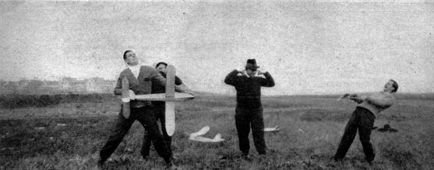
Simplicity of construction and flying are the outstanding design features. In the hands of an experienced flyer, consistent results are assured. Typical case is the slightly modified version of this model built for the 1938 contest season. Shortly after we posed for the photo showing us winding the model, I launched the model for an out-of-sight flight of 18 minutes. This happened during January when thermal currents are mighty few.
Only one fundamental change was made in the design when preparing it for "the present contest season. The fuselage was turned on edge and the wing was mounted on a bamboo‑wire saddle instead of resting flat atop the fuselage. These changes are not included in this article, however. Plans included in this article show the model exactly as it was on its winning flight last year.
CONSTRUCTION
Bend the 1/8" square longerons to the outline - which can be drawn up full size using the dimensions given in the reduced size drawing. The dimensions given in the side view of the fuselage extend from the outside edge of the longeron to the reference line. Build up two identical side-panels. Cut the fuselage upright braces and insert them between the longerons.
In joining the two side-panels, note that the width is given at only four points. (Top view). Hold these dimensions but allow the panels to take a natural curve between these stations - filling in the cross-braces to fit.
After the cement joints are firm, round off the outside edges of the fuselage with sandpaper. Fill in the front and rear ends of the fuselage with 1/8" sheet balsa - as shown by the shaded portions in the drawing.
The tail boom joins the fuselage with a plug which fits inside the fuselage. The plug is cemented inside the longerons of the tail boom. The other end of the plug fits inside the rear of the fuselage. The boom is kept in place with strips of Scotch tape.
The nosing is cut from a block 1-1/8 x 1-1/4 x 1-3/4" It fits inside the fuselage in pluglike fashion. It is held in place with a rubber band which fits through a notch in the nosing and is fastened to wire hooks on each side of the fuselage at the third upright brace.
Propeller bearings are made of sheet brass. The ends are pointed and bent to a U-shape. Bearings are pressed into both the outside and the inside faces of the nose plug. These bearings should be set to hold the propeller shaft at 2 degrees negative thrust and 1 degree right.
WING
The wing is made in three 14" sections. Each section is completed ready for covering before joining. The center section is flat. The two outboard sections are raised 4-1/2" at the tips. Note in the drawing the outer section has been shortened to meet space requirements. Dimensions supply all the necessary information, however. 1/32" ribs are used throughout with the exception of the end ribs of each section - where the extra strength of 1/16" ribs is necessary for joining the wing sections. For additional strength, balsa triangles of 1/8" sheet are cemented inside the end rib. Note that the 1/16" square spars are curved back at the tips. This strengthens the tip and makes covering easier.
ELEVATOR
Construction follows that used in the wing. The sizes of spars and edges are the same. The drawing gives the full-size rib shape.
RUDDER
The lift section used in the elevator is used in the rudder. The flat surface is on the right side (looking forward). By using the airfoil in the rudder it is possible to set it at zero degrees and still obtain the necessary turn.
PROPELLER
The block size is 1-1/2 x 2 x 16". The blank layout is shown in the drawing. The blades are cut to taper in thickness from 1/4' at the hub to 1/16" at the tips. Each blade is given about 1/8" camber in the rear face. The entire propeller is sanded smooth and doped to a high luster. The free-wheeler and propeller hub guard are bent from 1/16" sheet brass. The free-wheeler is secured to the front of the propeller. A piece of silk wrapped around the hub will reenforce the cement - holding the free-wheeler firmly in place. The propeller hub guard fits around the rear of the hub and protects it against wear. The propeller shaft is bent from heavy wire. 1/16" diameter piano wire will insure smooth operation.
POWER
Eighteen strands of 1/4" flat brown rubber were used. The motor length is 45 inches: Treat the rubber with prepared rubber lubricant - glycerin (drug store variety) can be effectively used.
COVERING
Covering is regular model tissue. After water-doping, follow with one coat of thin dope on the wing and tail surfaces and two coats of heavy dope on the fuselage.
FLYING
First glide the model, launching it from about 6 feet. If the model stalls, move the wing back a slight amount. If it glides too steeply, move the wing forward. The wing position shown on drawing is only approximate - it will vary with each particular model. Note that a 5/32" incidence block is inserted between the wing and the top of the fuselage.
After a satisfactory glide, wind the motor about 100 turns and launch it into the wind at about, a 65 degree angle. The model should fly against the torque (right turn) because of the offset thrust and the airfoil shape in the rudder. The model has a steep climb and makes about 25-foot-diameter circles while climbing. In the glide the circles are larger - about 100 feet.
The secret of a long flight is power. The photo very amusingly brings out this point. However, the initial stretch given to the motor is not at all exaggerated. Note, too, that winding is done through the front of the fuselage. The propeller shaft can be bent to fit the winder, making it possible to wind without taking the rubber off the shaft.
On the winning flight in Akron about 1000 turns were stored in the motor. The model climbed at a 45 degree angle for about 1 minute. After the power stopped, the model leveled out and started to glide. But it continued to gain altitude with the help of a thermal current. The model was just a speck in the blue sky after 41:15 when heavy traffic and an unfortunate curve in the road brought an end to the chase which we were staging along the roads outside the city.
The 1938 version of this stick model showed great promise. As mentioned earlier in the article, it turned in a flight of 18 minutes in January. In March it went out of sight again after 34 minutes and 27 seconds. The model was returned after both these flights. In calm March air, it averaged 3-1/2 to 4 minutes on every flight. These flights were in the current‑free air of late evening.
MATERIAL REQUIRED
(Balsa unless
otherwise noted)
Fuselage
| 9 pcs. | 1/8 x 1/8 x 36" | longerons and bracing |
| 1 pc. | 1-1/8 x 1-1/2 x 18" | fill-in for fuselage ends |
| 1 pc. | 1-1/8 x 1-1/4 x 1-3/4" | nosing |
| 1 pc. | 7/8 x 7/8 x 1-1/4" | tail plug |
| 1 pc. | 1/16" diam. x 12" piano wire | shaft and rear hook |
| 1 pc. | fine wire | nose plug attachment |
| 1 pc. | 1/16 " sheet brass | propeller and nosing fittings |
Wing
| 18 pcs. | 1/16 x 1/16 x 14" | spars |
| 3 pcs. | 1/8 x 3/8 x 14" | trailing edge |
| 3 pcs | 1/8 x 1/8 x 14" | leading edge |
| 1 pc. | 5/32 x 1/2 x 3-3/4" | incidence block |
| 5 pcs. | 1/32 x 5/8 x 24" | ribs |
| 1 pc. | 1/16 x 5/8 x 16" | ends ribs |
| 2 pcs. | 1/16 x 1/16 x 12" (bamboo) | tips |
| 1 scrap pc. | 1/8" flat | end-rib reenforeements |
Elevator
| 5 pcs. | 1/16 x 1/16 x 24" | spars |
| 1 pc. | 1/8 x 1/8 x 19" | leading edge |
| 1 pc. | 1/8 x 3/8 x 20" | trailing edge |
| 2 pcs. | 1/16 x 1/16 x 11" (bamboo) | tips |
| 2 pcs. | 1/32 x 3/8 x 24" | ribs |
Rudder
| 5 pcs. | 1/16 x 1/16 x 8‑3/4" | spars |
| 1 pc. | 1/8 x 1/8 x l0" | trailing edge |
| 1 pc. | 1/8 x 1/8 x 6" | leading edge |
| 1 pc. | 1/16 x 1/16 x 11" (bamboo) | tip |
| 1 pc. | 1/32 x 3/8 x 24" | ribs |
Additional Items
| 3 sheets | tissue | |
| 2 ounces | dope | |
| 2 ounces | cement | |
| 1 propeller block | 1-1/2 x 2 x l6" | |
| several washers | ||
| 68 feet | 1/4" flat brown rubber | |
| several strips | Scotch or masking tape |
Scanned From September 1938
Air Trails
![]()
![]()
[ Home ] [ Previous Plan Pages ] [ Special
Things ] [ Earl Stahl Plans ]
