The Plan Page
[ Home ] [ Previous Plan Pages ]
[ Special Things ] [ Earl Stahl Plans ]
gt-hunter1@home.com
A Fine Flyer That's Easily Made
Here Is a Model Plane That
Flies Consistently
Yet Which Requires Only the Simplest Operations to Complete
By RALEIGH T. DANIEL
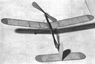
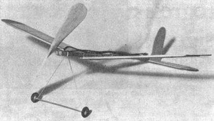
The pictures show the little ship ready to fly.
The large stabilizer gives stability
TO THOSE who are just beginning in the art of model airplane building or for those who have not yet enjoyed the results of completing a successful flyer, we recommend this model. The design is such that if the instructions are carefully followed, the machine will be easy to make accurately and to true-up. The necessity of obtaining these two conditions cannot be emphasized too strongly as the lack of them is the principal cause of failure to fly properly in all well-designed models.
We believe that many of the more advanced modelists will also want to build this plane because of its rugged construction, ease and economy of building and its consistent and dependable flying qualities. Its climb is remarkable and the stability (model's ability to maintain and regain flying equilibrium) is good.
There is a point which the writer wishes to mention to beginners; namely, the instructions to a working drawing are usually boiled down to a very minimum of words to save space. Hence, those who make up plans and instructions in their work are continually seeking to use expressions arranged in such a way that even the concise, the most logical way for the reader to see it, is the very meaning intended. But don't forget that due to the brief form, the true meaning often has to be "dug out." So it is advised that you study the plans and instructions in a manner to understand them as clearly as possible before starting work. That in general is a practice that will help rocket you to that upper strata of the experts!
List of Material Needed
Miscellaneous parts
Motor stick -‑ one 1/8 x 1/4 x 14" straight‑grained hard balsa that resists twisting.
one length of .028" straight music wire.
One 1/8 x 3/16 x 18" light balsa.
One pair of 3/4" balsa wheels.
Two 1/8 x 1/16 x 18" medium hard balsa.
Six 1/8" washers.
Two 1/16 x 1/16 x 18" medium balsa.
One bead.
One 1/8 x 1/8 x 7" light balsa for stabilizer spar.
One medium‑size thrust bearing.
One 1/8 x 13/32 x 4‑1/2" and one 1/8 x 1/8 x 1‑3/4", both hard balsa.
One propeller shaft.
One l/32 x 2‑1/4 x 2‑1/2" medium or light balsa for wing tips.
One sheet or less of tissue.
One 1/32 x 1‑7/8 x 5" medium or light balsa for stabilizer tips and for the fin.
Six feet of 1/16x1/30" rubber thread for the motor.
One 1/32 x 3 /32 x 4" bamboo for handing gear spreader bar.
Cement.
One 7" diameter machine‑cut balsa propeller.
Important:
A graphical description of how to carve a propeller appears on page 26 of the July issue of MODEL AIRPLANE NEWS. It may be helpful to you
The Wing
An old drawing board is ideal to work on or else get a flat and level, preferably wood surface of some kind. Sand the 1/8 x 3/16 x 15-3/4" leading edge spar to a rounded shape on one edge, see fig. 1, end view. Use sandpaper wrapped around a rectangular wood block. Sand the 1/16 x 1/8" trailing edge spar on one side to a wedge shape; see fig. 1, end view.
Lay out a full-sized drawing of the wing on your board. Now the wing spars may be put in place directly on the drawing and secured with thumb tacks or weights. Cut the 1/16x1/16" wing ribs to length and cement in place, all except the no. 1 ribs which are not put in until after the dihedral angle is fixed.
Set your compass to scribe a radius of 1-1/8" and mark the wing tips on 1/32" sheet balsa so that the wood grain runs with the wing span. Cut out and cement the tips in place. Be sure that your cement is not too thick, for if it is, it will not penetrate the surface crevices and get a real hold on the wood. Make several applications of cement (allowing time between to dry) on all of the various structures. The wing tips are braced with 1/32 x 3/64 x 2-5/16" bamboo strips "C," placed on the underside and cemented. It is necessary to cut a notch in rib no. 5 so that the brace may be imbedded in it. The end of the brace punctures into the front spar, see fig. 1.
When the wing is dry it may be removed from the board and remember that the top side of the wing was against the board while being made - see the underside structural view in fig. 5.
In order that the model may have lateral stability, the wing tips are raised to give the wing a "dihedral" angle. The method of doing this is clearly shown in figures 6 and 7. The spars are cut halfway through from the underside and cracked up into the position shown.
The wing is now placed on the drawing board and one‑half is held down flat with weights. A propeller block is then slid (absolutely straight) under the other wing half until the tip is raised 3-1/2". The dihedral blocks "D-B" which are 1/2" high by 1" long and 1/16" thick, hard balsa, are cemented to the inside faces of the spars as in figures 6 and 7, to permanently maintain the dihedral setting. These are thoroughly cemented and when dry the wing is taken up and the blocks "D-B" are trimmed down until they agree in shape with their respective spars. The no. 1 wing ribs are now cemented in place. The top of the wing is covered with tissue, using tissue cement as an adhesive.
Now make the wing center-block, assembled in fig. 2 and detailed in fig. 3. The center section of the assembly consists of a 1/8 x 1/8" balsa strip cut to length. The three parts are cemented together and when dry are cemented in place on the wing. Whereas this is a simple-to-make wing mounting structure, it is very rugged and when slipped on the motor stick, will accurately set the, wing at the proper angle of incidence.
Tail Unit
The fin is made of 1/32" lightweight sheet balsa and is cemented onto the left side of the motor stick as shown.
The stabilizer is made in the same general manner as described for the wing. The front and trailing edge spars are sanded to the shape similar to the wing. Cover it on top with tissue. In the exact center on top of each spar, trim off a small square of tissue where the spar will be cemented to the underside of the motor stick. To cement the two together, lay the stabilizer flat on the drawing board. The motor stick is then put in its proper place and held there by weights until the cement is dry. Apply several coats.
Miscellaneous
The "Can" is made of soft wire, about .020" size and the circular part is 1/4" in diameter. The hook "K" for holding the wing anchor band is of the same material. However, music wire could be used in either case but is harder to work.
The landing gear is made of a straight length of .028" music wire. Put the wheels on and bend the wire at right angles to form a hub cap, see figures 1 and 9. Now put in the bamboo spreader bar, cement and bind with thread. Use thread and cement in securing the landing gear to the motor stick. Attach the thrust bearing with thread and cement.
A 7" machine-cut balsa propeller is advised as a little sanding will prepare it for use and it can be bought for a small sum from any of the supply houses. However, anyone desiring to carve the propeller from a block may do so. If so, use a block 9/16 x 1 x 7" cut to the "X" type of blank.
A propeller shaft can be used for the rear hook "H" or one can be bent from .028" music wire. A tiny hole is made straight through the motor stick, 2-1/4" from the rear end and the straight part of the wire hook is inserted. It is then bent straight back along the stick and cut off; see fig. 9. Also note that the motor stick is tapered from where the stabilizer begins to 1/16" wide at the rear tip (1/16" in a length of 2-1/8"; it is tapered on one side only).
The wing is anchored by means of a small rubber band. This is done by looping the band around. the motor stick just ahead of the wing. It is then stretched rearwardly under the wing and hooked on each side of the wire part "K."
Three loops (6 strands) of 1/16 x 1/30", rubber thread are needed for the motive power. The rubber is looped around the prop shaft and rear hook and the ends tied together at the rear.
When the model is entirely assembled, try gliding it. Move the wing forward if it tends to dive and backward if it noses up, until the best glide is obtained. The technique of pre-flight test gliding a model is: release the plane in its natural gliding angle and at approximately its gliding speed, with the wing tips laterally level. Thus it will start on its glide with balance rather than in an unbalanced attitude. You should acquire this skill with a little practice. Select as calm weather as possible.
Now wind the motor up for a test flight. If it does not fly correctly, recheck and readjust it. Correct any error which you have made. If you have done a careful job, you will probably experience little or no difficulty in flying it, even though just having begun the "game."
Please remember this, that not just one in every few, but EACH model accurately built according to these plans will be a consistent and dependable flyer.
After finishing your adjustments, you may lubricate the motor and wind it to capacity with a winder, to see it climb up and away to give you thrills, aplenty!
Scanned From December 1935
Model Airplane News
![]()
[ Home ] [ Previous Plan Pages ] [ Special
Things ] [ Earl Stahl Plans ]