There's a sleek trimness about a modern military machine that shoots a thrilling tingle down your spine. This new Vought ship does just that - and she's got the stuff it takes to make a soldier. There's an element of mystery about our model Vought, too, since the original V-143 is a development of the fast Northrop fighter that disappeared into Pacific skies on that test hop about a year ago. A grand model, fellows - take it away!
|
|

|
|
|
|
EVERY model builder remembers that mysterious high-powered Northrop fighter that disappeared on a test flight last year, after being fitted with a retractable landing gear which lifted its top speed to over three hundred miles an hour. The story is still a favorite one among aero enthusiasts.
For a long time afterward, aviation attention was concentrated on the West Coast, for Northrop was expected to reproduce the strangely lost ship. But suddenly, on the East Coast, there appeared a sister craft, designated as the Vought V-143. Northrop, it seems, had found the capacity of its plant strained to the limit in the production of the now famous Northrop attack planes. Hence their plans, data, and technical dope on the missing craft had been turned over to the well equipped Chance Vought plant in Connecticut, and it was here that the newer ship has been built by Vought.
Many modifications were made in bringing out this new ship. Then spin trouble developed, so the rudder was enlarged. Cowl flaps were added also, and a lower horsepower engine was installed -an indication that the ship is meant for export. And so on - but the family resemblance to the vanished Northrop remains.
FUSELAGE
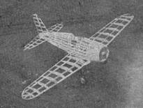
IN our model, emphasis is placed both on strength and lightness rather than on lightness alone, hence the ship is fast, but fully capable of resisting hard knocks.
Build the center section first, since this is used as a jig for assembly of the fuselage. Then cut out all fuselage bulkheads from 1/16" sheet balsa. Make two halves of each and cement them securely together. Cement bulkheads G, H, and J to the center section. Add the wide 1/8" by 1/16" stringer at the side, and the two 1/16" sq. stringers one above and one below it. Cement the remaining bulkheads to the stringers. Glue the rear hook in place and add the remaining stringers. It may be necessary to fill in between stringers with 1/16" sq. pieces at the end of the tail, in order to obtain the correct shape.
Build up the cowl front, add former E and the 1/16" by 1/8" stringers between D and E. Cover the cowl with 1/32" sheet balsa strips running lengthwise, allow to dry, and sand smooth. Add push rods made of pins with the heads cut off.
Cement the cowl to the fuselage. Carve the blocks which simulate the wheel housings, and cement into place.
PROPELLERS
BUILDERS of this model may use either of two types of propellers -- for display, the three-bladed scale prop which is standard on the original fighter, or the two-bladed airscrew for model flying. Full data on each type is given on Plate 1.
TAIL AND WINGS
IF the model is to be built for flying, the tail surfaces must be made as light as possible. Quite as important is doing a perfect job, so that the efficiency of the tail will not be spoiled by poor covering or warped surfaces. Probably the best way of obtaining a rigid stabilizer is to build that unit in one piece, then cement it to the fuselage before covering. This, incidentally, will simplify tissue filleting. The fin also mar be handled this way.
Wings are of standard construction. Make one right and one left, by making a carbon copy of the outline on a sheet of paper. Put another piece of carbon paper face up under the white paper, so that the plan is duplicated in reverse on the other side. Cement the outer panels to the center section with 1" dihedral on each side for a scale model, or 1-3/4" to a side for a flying model.
LANDING GEAR
ALTHOUGH it may look somewhat complicated, the landing gear is very easily built. First bend the wire ''backbone" in the proper manner, from the wheel to the point where it enters the wing. Do not put the last bends into it at this time. Wrap bond paper over the straight part of the wire, cementing between wrappings, and then before the cement is dry, mold the wrapping to a streamline shape with your fingers, and slide the completed fairing down over the lower bend in the wire as shown. Slip a length of 1/8" diameter aluminum tubing over the upper part of the wire. It may be necessary to stuff this with paper to make a tight fit. Wrap a small length of the lower end with paper and the upper part with heavy thread.
Dope this whole assembly black, and make the final bends which go inside the wing as shown in the side and top views. Cement the landing gear in place, and add the 1/16" sq. braces which hold it against the spar and prevent the joint from working loose.
The aluminum fairing is separate from the shock absorbing part of the gear, and is cut to shape and pushed between the two ribs at the junction of the center section and the outer wing panel. The indentation about half way up the fairing is made by ruling the aluminum with a round ended instrument such as a button hook, bearing down hard enough so that the desired depth of impression is obtained. Be careful to do this neatly.
COVERING
THE model may now be covered. The fuselage should be covered in short strips, especial care being taken at the fillets. Leave a panel open at the rear hook for installing a rubber motor. A flying model may be covered with blue tissue for the fuselage and yellow for the wings and tail, the whole plane lightly sprayed to tighten the tissue, and then given a coat of clear dope all over except for the stabilizer and rudder, which we want to keep as light as possible.
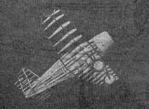
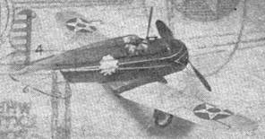
If it is desired to use colored dope, the correct color scheme is fuselage, army blue; tail surfaces and wings, army yellow; landing gear fairing, yellow. Details are black. As the ship is not in service, there is no authentic squadron insignia, but the model builder may desire to trim up his ship, and the photographs depict the craft with an insignia added by the author.
FLYING
BECAUSE of the balsa covered cowl, the ship is likely to turn out slightly nose heavy. This is to be desired, since the stability is greater than if it were tail heavy, and small adjustments can be made with the adjustable tail surfaces, or by doping the tail. About eight strands of 1/8" rubber will be required. Make most of the adjustments for lateral stability by rudder setting rather than wing warping, adjusting the model to fly in the manner that it normally tends toward (probably a left circle). As a last resort, if the model persists in spiral diving, the leading edge of the inner wing may be warped up slightly. Too much will cause the ship to spiral dive in the opposite direction, as the power runs out.