|
|
|
|
|
|
The Plan Page
[ Home ] [ Previous Plan Pages ]
[ Special Things ] [ Earl Stahl Plans ]
gt-hunter1@home.com
Build and Fly This Cloud Chaser
|
GOOD NEWS FOR GROUP LEADERS: Here is a rubber‑powered high performance model that can be built by your novice club members. Start the younger enthusiast off right - recommend this model and this MODEL AIRPLANE NEWS series to the less experienced flyers. A little encouragement and aid will go a long ways towards producing a 1940 national record holder in your group. |
By BRUNO P. MARCHI
|
|
|
|
|
|
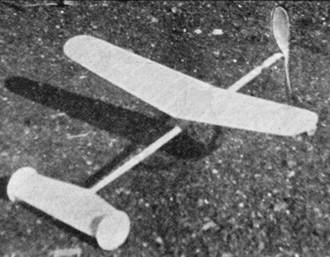
QUIET now! Tiptoe in and we'll show you the newest cloud chaser at rest. There you are -- isn't it a beauty?
With a faster climb than a rising stock market and a sweeter glide than a sea gull, this stick model, especially designed for novice builders, is certain to find favor with junior aeronauts everywhere.
Did you build that beginner's outdoor hand‑launched glider MODEL AIRPLANE NEWS presented in its June issue? Then you're all set to continue with this cloud chasing craft which carries on where the glider left off and introduces a host of new building kinks.
Interesting features of this stick ship are its easy-to-make twin rudders and choice of rise-off-ground or hand-launched flights. No "parlor gnat" is this . . . no, sir; it's a big, sturdy flyer thirty inches in wing span. Even if you've never tackled a plane of such proportions, don't hesitate a moment - for besides being a sweet soarer, this stick flyer is simple to build and provides splendid training for the heavier contest entries you'll be building soon.
Before starting construction, let's have a brief sermon on building models, especially outdoor craft:
With proper design, proper construction and proper adjustment, even the most inexpensive model will turn in good flights consistently. But a builder must utilize all three points in his work; so let's resolve to always choose a design with plenty of "flyability," build according to specifications and make all the proper adjustments before ever fully winding a model.
You built the beginner's outdoor glider? Fine, then you're off to a good start. Here's lesson No. 2, but it's not a tough assignment‑plenty of fun ahead for those who . . .
Select a medium-hard piece of 3/8 x 1/2 x 28-inch balsa for the motor stick. Measure in eleven inches from an end on one of the 1/2-inch sides and from that point taper the stick to 1/4-inch at the rear so tail end of stick measures 3/8 x 1/4 inches. With thinned glue, precoat front of stick where large thrust bearing will be glued on. Repeat procedure allowing cement to dry well between coats, filling the pores of the wood to provide a firm gluing base. Then using thicker glue, cement thrust bearing to stick.
While bearing cement is drying, bend the rear hook and propeller shaft from No. 14 wire. For this work a good hair of pliers are most necessary. The few extra pennies invested in pliers of good quality will repay with longer and less troubled service. Contest losses and crumbled fuselages caused by misshapen fittings frequently can be traced to poorly-bent fittings made with inferior pliers.
With fittings made, glue rear hook to motor stick, first precoating as with the thrust bearing. Then apply another coating of cement, bind with thread and - you've guessed it! - apply a final coating of cement.
After bearing is dry, bevel nose of motor stick as indicated by line M-N on plans. Precoat, then add extra nose piece shown, shaping with sandpaper and cementing liberally. Bind entire nose portion with thread and add several coatings of glue.
Make full-size drawings of wing and stabilizer. Stabilizer's leading and trailing edges and center piece are 1/16 x 3/16-inch balsa strips. Tip pieces are same size but are set on edge to give greater gluing, surface for the twin rudders. Diagonal stabilizer bracings are 1/8 x 1/16-inch balsa strips.
Bevel the two pieces which form the stab's leading edge, then pin these and the trailing edge down on your drawing and cut bracing to fit, making joints as indicated on drawing. Precoat all joints with thinned cement, using normally thick glue for final assembly. When cement dries, stabilizer is turned over and covered with white tissue. Grain of paper should run from leading to trailing edge, not lengthwise. Even though the covering is not to be shrunk, sun will tighten tip tissue and surface might warp were grain of covering tissue to run parallel to trailing edge.
If this is your initial covering attempt, don't be discouraged if it seems difficult. Keep trying until a smooth covering is attained. This is best done by applying thin dope to leading and trailing edges and end ribs, then stretching slightly larger piece of tissue over stabilizer frame and pulling taut with finger tips. Remember, don't shrink tissue with water or try to dope the paper.
Twin rudders are cut from 1/20-inch thick sheet balsa. Edges of rudders are sanded round, then glued, one to each end of the stabilizer, after precoating cementing surfaces. Be certain rudders are parallel.
When complete, entire tail unit is glued on motor-stick with the covered side of the stabilizer on top. The stabilizer rests flat on stick at no degrees of incidence and is off-set slightly, as shown, to make model circle to the left. This is known as circling the model with torque.
Wing spars are 1/8 x 3/16-inch strips. Pin them down on the full size panel drawing. Ribs are cut from 1/16-inch sheet balsa by using a metal or cardboard template. Using this template pattern, cut sixteen ribs each 1/8-inch deep. Leaving out the two center ribs, fit remaining ones into place between leading and trailing edges by cutting off rear portions until all are in place. Precoat cementing surfaces, then glue ribs in position. This method of tapering the wing by cutting a bit more off the rear of each rib while working outwards from the center eliminates stalling wing tips, thus adding to the efficiency of the main lifting surface.
Wing tips may be bent from 1/16-inch square bamboo or reed. Dihedral is obtained by raising one wing tip 6-1/2-inches off working board when other wing panel is flat on board. First precoat the surfaces which will touch, then glue the two panels together. Cement the two center ribs together and glue in place. After drying, again coat joints with glue.
While the wing is drying, bend the two wing clips from No. 14 wire to the exact shape shown on the plans. After wing panels are glued together, precoat wing spars where clips will be attached, then cement clips to wing. Bind clips to spars with fine thread and coat with glue. Clips should fit motor stick snugly, but not so tightly that wood is cut deeply by wire.
Using white tissue cover the top of the wing, one panel at a time, with the grain of the paper running parallel to ribs. A good wing-covering method is to start with a piece of paper slightly larger than the panel which it is to cover. With dope as an adhesive, attach paper to center rib. Then work slowly outwards towards the tip, a few inches at a time, applying dope to leading and trailing edges with a small artist's brush, smoothing out the tissue with the finger tips.
The landing gear which protects the propeller as well as permitting R.O.G. take-offs, is also bent from No. 14 wire. Wheels are 1-1/8-inch circles cut from 1/8-inch thick sheet balsa. Cut two circles for each wheel and after precoating glue together with grain of wool running opposite, as shown. Washers are glued to both sides of each wheel, then wheels are slipped on wire landing gear and ends of wire bent up. See illustration.
Instead of cementing landing gear to motor stick, thin rubber wrapped around the wire and stick holds landing gear in place. This permits gear to be quickly removed for hand-launched trials.
Final phase of construction is one of the most important. It has been wisely worded: a propeller can make or break a model. The prop for this cloud chaser is carved from a balsa block 1-3/4 x 1 x 12-inches in the four steps illustrated, or a 12-inch, machine-cut, partially-completed prop may be finished off and used. It is quite possible that some builders might make use of both types of propellers and compare performances.
In either case, the prop shaft is bent to shape shown from the same size wire as the other fittings. The shaft is cemented in place and several flat washers or a single ball‑bearing washer is placed between the propeller and thrust bearing.
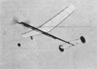
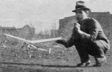
For trial flights your cloud chaser may be powered with eight strands (four loops) of 1/8-inch flat rubber which has but little slack. After adding rubber, adjust the wing on the motor stick until a smooth glide is evident -- then move the wing clips back about 1/16-inch and hand-wind the motor to a double row of knots.
With this power the model has been found to rise-off-ground or climb from the hand and turn in creditable flights. If model stalls in flight move wing back slightly; if take-off is slow try moving wing forward.
Should the eight strands of rubber prove insufficient to send the ship skyward in a suitable climb, add extra loops until a fast, even climb is obtained. Fully wound, with a right-hand prop, the craft may dive in on the left wing. To remedy this, increase the incidence of the left wing by bending up the leading edge and bending down the trailing edge. This is best done by bending the wire clips with pliers instead of breathing on wing. Known as "wash-in" this adjustment is one of the first to be found in the expert's bag of tricks.
When the cloud chaser is correctly adjusted it will be apparent that the model is a high and stable flyer; so unless you're out in the wide open spaces, it may be advisable to have the plane slightly underpowered. Remember that a plane in the hand is worth two in a tree.
When good flights become "old stuff" try experimenting with various sizes of rubber and loop lengths. Then fly the model with larger propellers and compare the duration of hand-launched with R.O.G. flights.
But either R.O.G. or hand-launched -- you're bound to like this big sturdy flyer.
Table of Approximate Weights
|
Wing |
.30 ounces |
|
Stick |
.56 |
|
Landing gear |
.15 |
|
Propeller |
.19 |
|
|
1.20 ounces |
|
Rubber |
.50 |
|
|
1.70 ounces complete ready to fly |
Required Materials
Balsa Wood
|
(1) |
3/8 x 1/2 x 28 inches. |
|
(2) |
1/16 x 3/16 x 18 inches. |
|
(4) |
1/8 x 3/16 x 18 inches. |
|
(2) |
1/8 x 1/16 x 18 inches. |
|
|
Half sheet of 1/20‑inch sheet. |
|
|
Half sheet of 1/16‑inch sheet. |
|
|
Half sheet of 1/8‑inch sheet. |
|
|
Block 1‑3/4 x 1 x 12 or (12‑inch machine cut prop blank). |
|
3‑ft. |
No. 14 wire. |
|
|
Large thrust bearing. |
|
14‑ft. |
1/8‑in. flat rubber. |
|
|
1/16‑in. Bamboo or Reed (12 inches). |
|
|
Sheet of White Tissue. |
|
|
Dope, Cement, Washers, Thread. |
Scanned From December 1938
Model Airplane News
![]()
![]()
[ Home ] [ Previous Plan Pages ] [ Special
Things ] [ Earl Stahl Plans ]