|
|
|
|
|
|
|
|
|
The Plan Page
[ Home ] [ Previous Plan Pages ]
[ Special Things ] [ Earl Stahl Plans ]
gt-hunter1@home.com
How to Build A Gas-powered Camera Model
PART NO. 1
Complete Information and
Plans From Which
You May Build a Plane That Will Take Aerial Photos
Or Serve As an Efficient Contest Model
By ELBERT J. WEATHERS
|
|
|
|
|
|
|
|
|
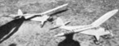
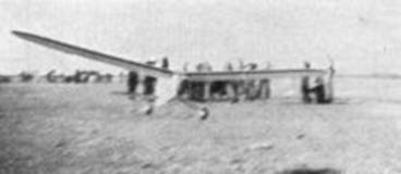
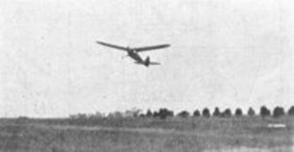
HERE, Mr. Gas Model Enthusiast, is a plane which has been thoroughly proven from several important angles. It is a ship of 8 foot wing span possessing the much sought after characteristics in present day gas models. As shown by past experience, it safely holds its own whets being judged for construction, general design and clean lines in a precision contest. The takeoff is very even and graceful and the climb, with the engine wide open or fairly much so, is nothing short of spectacular, considering its size. It has been observed on many occasions "going upstairs" at an angle approaching 30 to 35 degrees. The Grant X wing section and flying weight. (with full equipment, 5 lbs.) obviously have a lot of bearing oil this feature. On the other hand, the engine can be throttled way down, giving flights very similar to a Taylor Cub. Thus is the flexibility with it in flight. The glide is super flat and soaring on the mildest thermal is common. Under gliding conditions, the forward speed is very slow, and when ready to finally land, it comes in as gentle as a kitten, with little or no bounce.
The writer's original job was designed to have a perfect glide with both the wing and stabilizer in a fixed position and each absolutely neutral, relative to the neutral line of thrust. In other words, the only adjustment that has ever been made to it has been that of the tab in the fin, to adjust it for the wide circling to the right, after the motor cuts. Should anyone, upon completion of the model, find that gliding adjustments are imperative (which is a remote possibility if plan: are carefully followed), it is suggested that small sheet aluminum tabs be made and installed on the trailing edge of the stabilizer to compensate.
Each wing panel slides out of the center section after lock pins are removed and the tail surfaces detach likewise, as one unit insuring maximum ease of transportation to the flying field.
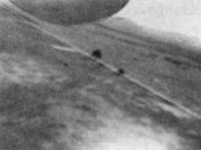
The feature of being able to take aerial photos should prove of enough interest in itself to urge most gas modellers to try the model. It is probably the first gas model to obtain worthwhile aerial photos. A standard Univex Model "A" camera is employed for this (very inexpensive, easy shutter action, and light weight) and makes surprisingly clear exposures considering the lens and flying speed (under power) of the model at the time of shutter action. When installed as shown, the left wing panel of the ship is included in the upper portion of each "shot," adding to the realism. This is clearly shown in the aerial pictures included in the article. The possibilities of taking photos from the air of gas model contests as your entry is flying overhead might also be mentioned in this connection.
Specifications
Wing span 8 ft.
Wing chord 10-1/2 in.
Wing area 967.8 sq. in.
Wing loading .76 lb./sq. ft.
Aspect ratio of wing 9 to 1
Overall length 4 ft. 10-1/2 in.
Stabilizer span 2 ft. 9 in.
Stabilizer area (21% of wing area) 203 sq. in.
Fin area (8-1/2% of wing area) 84 sq. in.
Dihedral 6-1/2 degrees
Tread 1 ft. 3 in.
Moment arm (40% of wingspan) 3 ft. 3 in.
Flying weight (complete with camera & film)
5 lbs. 2 oz.Power Brown Jr.
Timer Autoknips
Climb per minute in still air 250 to 300 ft.
Fuselage
First lay out all parts of the plane, full size, by enlarging from the assembly drawing, making use of all dimensions as given. Show location of all vertical or diagonal members as well as spars, formers, etc., on your working layouts.
Begin the model by first constructing the fuselage. Make two side frames to begin the fuselage. (Shown in shaded lines.) The longerons are 5/16" sq. and should be of hard balsa. Use firm balsa for all bracing. Secure longeron stock in one length if possible, so as to avoid splicing. However, if this has to be done, merely make a long tapered splice with balsa sheet bracing on the two inner sides of the longeron. It will be necessary to steam the lower longerons at the nose in building the frames. Do not forget the removable door frame which is shade at the same time, where shown, in the frame to be on the left side. When both are dry and sanded smooth on their outer sides, build them together in the usual manner, pinning each upside down on the workbench. For clarity, no diagonal bracing has been shown on the top and bottom of the fuselage frame. This is to be 1/8" sq. balsa, installed from, the wing mounting block to the rear end of the frame. See photograph showing this part completed.
The next step is to build up the top, rear section of the fuselage, from the cabin back. Start it by constructing the sheet balsa covered "box" upon which the rear part of the center wing section is to be attached. Install four corner uprights of 3/16" sq., followed by the filling in of all sides (except the bottom) with 1/8" sheet balsa fillers. This must be very firmly attached to the fuselage. Cut two 1/4" sq. hard longerons and install them as indicated. Complete the top rear section by putting in all the vertical bracing, which drops down from these longerons to the exact vertical spot on the fuselage frame, be it on a cross-brace, main longeron, or both.
Cut from 1/4" sheet balsa of firm grade the rear anchorage for the motor beams. Install it in the frame so as to receive the hardwood motor beams when ready. Install two lengths of extra hard balsa, size 1/4" x 1/2", to mount the landing gear on, where shown. The actual installation of the landing gear will be made later. Now cut the nose formers Nos. 1, 2 and 3. Nos. 1 and 3 are 1/8" sheet balsa, while No. 2 is made from 1/16" sheet stock. After each has been cemented in position, cut some lengths of 1/16" x 1/8" balsa from sheet stock for the nose stringers. Each is cemented in place as shown. On former No. 3, all stringers are cut at an angle and are cemented on the underside of it, with the exception of the top center one, which is inserted in the notch provided. The firewall may now be cut and installed. Use very hard balsa of 3/8" thickness for this. Remove two rectangular holes, the size of the motor beams, and all other wiring holes shown. The stringers on the sides of the fuselage are cut from 1/16" sheet and have a long taper from each end to the middle. Cement them where indicated. The top stringer must be made later. The method of making the spring leaf tail skid is simple; the drawing of this part is self-explanatory. It is then installed in its correct position, first being fitted to a 1/8" sheet balsa filler block which is cemented in place securely. Use metallic type cement to anchor the skid to the block.
The landing gear is made next. Form three frames (front side, rear side, and center shock strut) from 1/8" spring piano wire, using vise and hammer, laying each one over full size templates to compare. Install the front side frame first, on the balsa brace in fuselage. Use metallic cement and binding of copper wire abundantly, and also make corner braces to put against the main mounting piece. Next, install the rear section in same manner. Bind with the copper wire, both at the fuselage and at the axles. The center shock strut is of course held in position at each axle. Solder well to make a good union at each crotch, bound first with copper wire. Cut 2 sets of landing gear ribs from 1/16" sheet balsa and put them in landing gear with metallic cement.
The two hardwood motor mounting beams can be made next. Each is size 3/16" x 15/16" x 7-1/4" and should be made of a hardwood with the necessary "spring" in it. Black walnut is recommended for this, although maple or teakwood will do. Drill each one to take the metal plates, which serve as the actual motor and tank mounting. Then slide them through the slots provided in the firewall and the rear motor beam anchorage, using metallic cement very generously.
The aforementioned plates should be made as the next step. See plans for detail. Each is mounted on the wooden beams with sets of screws and nuts, of the type designated in plans. The engine and tank holes shown in the plans are for the Brown Jr. engine with old-style tank and should be altered slightly for the new type Brown tank. Also, if a different make of engine is to be installed, merely alter the plate itself, where bent at right angles, to secure the proper spacing.
Carve the lower portion of the nose block from a medium hard balsa block, removing only enough wood from the interior to allow the engine, engine timer and tank to sit in position without touching. It is left solid for a good reason - to absorb any severe shock to which this area may be subjected. The top section of the nose block or engine cowl, is made from a solid balsa block, but must be nothing more than a shell with thin walls. It is used on the original merely for added appearance on the ground or photographs, never being in place when the plane is flown. This, however, can be used for flying just as readily. Cut holes in it as shown, to allow for sliding over the cylinder, needle valve and spark plug cable.
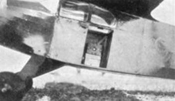
The engine accessories can be installed at this time. The battery box is simple to construct and is cemented to the 1/16" sheet balsa cabin floor, between the camera mounting and condenser. The condenser is also mounted on the floor between the battery box and the coil. Mount the coil with two supports as shown, in a vertical position against the rear motor beam anchorage bulkhead, about 1/2" away from the floor. Make sure the high tension line (to the plug) is on the top. Study the wiring diagram on drawings, wiring up everything as shown, with the exception of the Autoknips timer, which comes later. Also put in the main switch and booster plugs in the right side of fuselage where indicated. Use the small lacquer finished stranded and tinned wire if possible, laying all runs out on the floor in systematic fashion (spot with cement). The camera mounting is built up from 1/16" sheet balsa, being directly in front of the door in the left side of the fuselage. (Pictures taken straight out through open doorway.) Lay a length of 1/8" sq. balsa on the outer top edge of the mounting to insure that the camera will be tilted at the proper angle to include left wing in photos. The Univex camera is held in position by a strong rubber band which hooks from one side of camera mounting to other. Round off the lower fuselage longerons with a plane and sandpaper.
To complete the general construction concerning the fuselage, construct the fin stub and fuselage extension (actually part of the fin). This is where the tail surfaces detach as a unit. Cut the front sections of the ribs (installed over fuselage proper) from 1/8" sheet. Install two lengths of 3/8" O.D. aluminum tubing in the front and rear sections being constructed. Use metallic cement for this. Cut and cement in place the 1/8" sheet balsa fillers, in the fin base. When this unit is complete, ready to take the tail surfaces, make a paste of corn starch, clear lacquer (or dope) and aluminum powder, using it to make a generous fillet at the junction of the fin stub and fuselage.
Center Section of Wing, Windows and Timer
Begin the center section of the wing by first making two spars, each built up from three separate pieces as shown. Use 1/8" hard sheet balsa for these. This method takes care of the dihedral angle in the spars with a great safety factor. Cut four of the full size wing ribs from 3/16" sheet balsa. Leave the underside of two of them flat, for over the fuselage. The leading edge is 5/16" sq. (three sections), while the trailing edge is 1/8" x 1/2", tapered. Drill 3/8" holes in the four ribs to receive the 3/8" aluminum tubing. Be accurate in this operation. Cut the lengths of tubing. When center section is built, install the tubing with metallic cement. Follow with the fillers in the center section, which are 1/16" and 1/8" sheet. Now mount the wing center-section on the fuselage. It is supported at the leading edge by the two vertical window struts at that point. Cement it (using pins here and there) in place with the utmost care, noting that it is in perfect alignment with fuselage. Anchor the forward vertical braces most securely. Add the center cabin window braces next.
Paint the whole cabin area, where "raw" wood is visible, with a colored dope. Also paint the cabin roof (formed by center section) and nose former No. 3. Cut a length of 1/8" O.D. aluminum tubing and cement it in place in the center, between the wing center-section and former No. 3. The windshield can now be installed, followed by the side cabin windows. Use .015" celluloid of good quality. Refer to the windshield template on drawings. Install all celluloid with cement, using pins to secure till dry.
The Autoknips flight timer should be built in place at this point. (This timer, its use pioneered in the west, is rapidly becoming known to eastern gas modellers.) Secure it in the position shown, in center section of wing, on a sheet balsa support, making certain that the top surface of the case is just flush with the two center ribs at that point. Make the switch as shown, being certain it functions properly. Also, it will be necessary to make an extension for the timer brake, to operate this through the covering. Solder a length of galvanized sheet metal, as shown on plate 1, endways against the timer hook, which travels into the case as the timer winds down. A small hole should be in the opposite end, so the string shutter cable to the camera can be attached. Make or buy a small pulley (about 3/8" diameter) and install it against the motor beam bulkhead, on the left side of the fuselage. It should be in line with the timer hook extension. The camera shutter cable then leads from the extension on timer arm, through the cabin ceiling (at about 45°angle), straight down to the pulley and then straight back to attach on the extension on the camera shutter. (Merely a pin with loop on end, soldered on.) The procedure used in taking the pictures is described at end of article.
Now form the 1/16" stringer which extends along the top of the fuselage, in the center, from the flight timer to the fin stub at the rear. Cement it in place. Also cut and install the wing fillets at the trailing edge, between the fuselage and center‑section of wing. Each is cut from 1/16" sheet stock and extends 2" each way from the corner and is actually a quarter circle around the rear edge. After cementing each against the two uppermost fuselage longerons and the wing stub trailing edge, fashion two filler pieces (about 3/16" deep at center) which are installed over the two center wing ribs and extend back on the fuselage longerons. These should be cut with along tapered curve to fit and allow for a good blending of the wing center-section.
Scanned From May 1938
Model Airplane News
![]()
![]()
![]()
![]()
[ Home ] [ Previous Plan Pages ] [ Special
Things ] [ Earl Stahl Plans ]