|
|
|
The Plan Page
[ Home ] [ Previous Plan Pages ]
[ Special Things ] [ Earl Stahl Plans ]
gt-hunter1@home.com
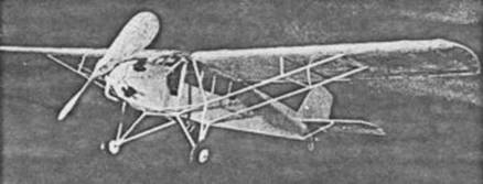
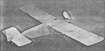
Corrigan's Crate
By DAVID D. GRANT
A Flying Exact Scale Model of the Plane
That Flew "The Wrong Way"
|
|
|
JULY 9, 1938. Sure now and it's myself that's thinking that was a great day for the Irish. For it was then that Douglas Corrigan made the broad blue Atlantic look like a duck pond, by flying across the damp spot. And the reason he made the big drink look particularly silly was that he blithely hopped over it by mistake, (or was it?) in a more or less dilapidated antique of the gone but not forgotten pre‑depression days. His old Curtiss Robin was never built for such gallivanting, but with an Irishman's luck ‑ Well, I know where he can get a Bleriot XI to try a hop to China.
Anyway, in spite of its age, the Robin is a fine crate; and what is particularly important to us, it lends itself perfectly to modeling. It is a model that is smooth and stable in flight, and unusually simple to build. For what could be easier than a model with straight wings and tail and a box car fuselage? And it has a high wing for stability, clean lines for appearance and plenty of bracing for strength.
So dust off the work‑bench, roll up your sleeves and settle down for a pleasant session of model building.
First read over the instructions carefully, study the drawings, and when you have a good idea of the whole job, start in.
Join the two sheets containing the fuselage drawings and with pins set up the jig for the longerons. Build the sides in the jig in the conventional manner, completing them as far forward as the front struts, on the board. Let the lower longerons extend far enough to reach B2. The three short pieces marked D are parts of the door frames and are on the right side only. All fuselage parts are 1/16" square balsa; except the wing carrier, which is 1/16" flat, and the tail post which is 1/16" by 1/8", and not put in until assembly.
While the side frames are drying, make the bulkheads, B1 and B2. B1 is cut from 1/16" flat balsa as shown on the drawing. B2 is built up. The rear half is built from four strips of 1/16" flat, all sides straight, with the side pieces butting against the top and bottom strips. The front half is built of 1/32" flat, with the side and bottom pieces curved, forming a flange; the top and bottom pieces butt against the sides. Thus when the front and rear halves are laminated together the corners are cross lapped for strength.
Assemble the fuselage sides in the conventional way, with cross members cut to lengths as shown in the top view, of 1/16" square wood. When dry, add 1/16" square all around inside the frame at the front station, to brace the fuselage against landing shocks.
Glue B2 to the lower longerons, and carefully build up the windshield frame to it. Note that the flanged side of B2 faces forward. Next make a jig from two pieces of 1/16" flat, as wide as the distance from B1 to B2, and lightly "spot weld" them to B2, with their ends touching at the top to form a "Vee." Then spot BI to them, lining it up carefully. When dry, cut and fit in the 1/16" square nose stringer strips around the top and sides. Leave the two bottom strips, which run from the corners of B2 to the bottom center of B1, until after the jig is removed.
Blank out the nose block from 1/2" thick balsa, and before any rounding is done locate the center lines and drill the hole for the bearing block. Since this hole is at an angle lay the block on the table face up and block up the lower edge 3/32". The table line is shown dotted in the side view. Drill a 1/4" hole with the drill held vertically. Then the carving can be completed in the usual way.
The cylinders are cut from 1/4" round balsa and wrapped with thread to represent cooling fins. Fit them carefully to the nose block as shown in the front and side views. The rocker arms are cut from 3/32" half round balsa and glued to the tops of the cylinders. Push rods are bits of wire or bamboo and slope slightly back and toward center from the rear ends of the rocker arms. The intake pipes are short scraps of 1/16" round, sloping back and toward center from the upper left side of the cylinders.
Cut two rings of 1/8" flat wood for the exhaust manifold ring, laminate them together, carve them down as shown in the drawing, and glue to the front of the nose block. Then the exhaust pipes can be run from the upper right side of the cylinders to the ring. These are also 1/16" round wood. The exhaust stack can be carved from 1/8" flat balsa to the shape shown in the side view, sanded to a round section and glued in place. The nose block can then be glued to B1.
The wing ribs are all cut from 1/32" flat balsa except the root and outer strut attachment ribs, which are 1/16" flat. The spars are 1/16" by 1/8" balsa, and the leading edge is 1/8" square. The trailing edges are tapered to an edge from 1/16" by 1/8". The tips are cut from 1/16" flat. Aileron spars are 1/32" flat. The wing is assembled in the usual way and cracked at the first rib for dihedral. The tips are raised 3/8".
The tail surfaces are built from 1/16" square, and the curved edges are cut from 1/16" flat. These can be made stationary or movable, as you prefer. The rudder is shown with movable construction, and the elevators fixed. The dotted lines show the outline for a scale stabilizer and elevator, the solid lines show the flying surfaces.
Wing struts are cut from 1/16" by 1/8" streamline stock up to point of attachment of strut V. Struts W. Y and Z are 1/16" round wood. The vertical shock strut and the front "Vee" strut of the landing gear are 1/16" by 3/16" streamlined. All other struts are 1/16" by 1/8". Strut lengths are all as shown in the front view, except those shown by separate drawing (F and landing gear).
The wheels are either of hardwood, 1‑1/8" diameter, or laminated from two disks of 1/8" flat hard balsa. The axles are music wire, cut in a single piece which runs up the front Vee struts and across the bottom of the fuselage.
The propeller is made in the conventional manner, as shown on the drawing. It is assembled to the nose plug on a music wire shaft with three or four washers between. The nose plug is fitted with a bushing to act as a bearing.
The tail skid is cut from scraps of 1/16" balsa, the rear strut being wrapped with paper to represent a shock absorber. The tail hook is bent from music wire and attached to the tail post.
Cover the model with fine tissue, leaving a space open at the tail in the bottom for threading the rubber. The cowl, from B2 forward, is covered with bond paper. The windows are cut from thin celluloid and glued in place after covering.
Assemble the model carefully, being sure that each part is carefully lined up. Cut away the tissue wherever a strut attaches.
Spray lightly with water to tighten the tissue and when dry give the entire model a coat of cream dope. The motor and tires are black and the exhaust pipes and ring, as well as the propeller, are silver. The doors may be outlined with India ink; also the controls if they are not movable. The license numbers, if you care to put them on, are NX9243, on the upper right and lower left wing surfaces and both sides of the rudder.
Power the model with three loops of 1/8" flat rubber and when you have a nice day for flying, take it out. Try it first in high grass, with half winding, until it is balanced and adjusted. Then give it the works and let her go. Good luck and happy landings!
Scanned From January 1939
Model Airplane News
![]()
![]()
![]()
[ Home ] [ Previous Plan Pages ] [ Special
Things ] [ Earl Stahl Plans ]