|
|
|
|
|
|
|
|
|
The Plan Page
[ Home ] [ Previous Plan Pages ]
[ Special Things ] [ Earl Stahl Plans ]
gt-hunter1@home.com
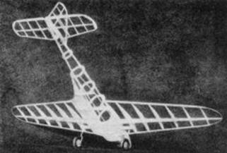
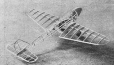
A Miniature Fairey "Battle"
How You Can Build and Fly a Carefully Detailed Model
of England's Latest Bomber Fighter That Soon May See Action
By ROBERT V. SMITH
|
|
|
|
|
|
|
|
|
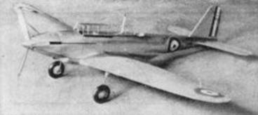
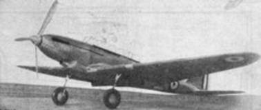
POWERED with the new Rolls Royce "Merlin" engine which develops 1,000 horse power, this raider courses through the skies at better than 260 m.p.h. The "Battle" is an all-purpose job complete with radio, light bombing equipment and guns. With the advent of super bombers and pursuits it was found necessary to develop a plane to keep up with them, so here it is - modeled perfectly in a stable flyer.
Fuselage
Begin the body of the model by cutting out the bulkheads from 1/16" sheet balsa; laminate bulkheads DD and EE so that they will be strong enough to take the wing as they form the wing stubs. The main longerons are 1/16" x 1/8 hard stock. Carve from two soft blocks a right and left wing fillet block Q. The blocks measure 5/8 x 7/8 x 1-1/4" and should be notched to receive the 1/16" square balsa stringers for filleting the wing. Make a radiator block from a 3/4 x 1-7/8" square soft block and shape it as shown; the bottom of it is rounded to the shape of former RR. The small block between formers BB and RR is the oil radiator. From two blocks 7/8 x 1-3/4 x 1-7/8" glued together, carve the nose block, then break open and hollow out as shown; the two blocks are now cemented back together and the whole sanded with ten nought paper.
When all the fuselage framework is assembled. it is covered with 1/64" soft sheet balsa. This is not as hard as it would seem at first but it does take longer than the conventional paper covering job. The wing stub ribs (No. 7) are 1/16" stock and cemented firmly to block Q and formers DD and EE.
Start the covering job by working small sheets around this stub rib and into the fairing stringer back to former GG: when these sheets are dry trim them and cut the gradual carve shown between the trailing edge of the stub rib and former GG. The upper part of the body between formers CC and FF can be covered in one piece and the two cockpits cut out later. Two pieces of sheet will be sufficient to cover the stations between FF and II. The very last section can he covered with two sheets, one on top and one on the bottom. The cross section J is elliptical in section and after this is covered round the back part to the shape in Sheet 2. The small fillet in section CC and DD can he easily put in by the use of a mixture of balsa dust and cement. The whole fuselage should now be doped with a wood filler solution and sanded with ten nought paper when dry. Two coats of silver paint will do for the coloring. The pilot's enclosure is made up from two 1/16" square balsa sticks on to which are cemented eight frames (see sheet 4). These can be made either from bamboo or soft wire. After this "coop" is dry it can he covered with cellophane and then glued on the body at the proper position. A little black paint will trim it up considerably.
Wing
Cut the wing ribs from 1/32" stock except for the end ribs, No. 7, which are cut from 1/16" material. The spar is tapered from 1/16" stock to the size shown on sheet 3. Round one edge of the 3/32" square leading edge and taper it slightly so as to fit the smaller ribs nicely. The triangular cross-sectioned trailing edge is cemented to the ribs and notched to receive the 1/32" square bamboo tip. Tilt ribs 7 a little to give the wing some dihedral. A smaller spar is cemented in ribs 6 and 7 for the landing gear attachment. Cover the wings with colored paper; the original model had orange wings, but practically any color will go with the silver fuselage. The bottom section where the landing gear fastens should be left uncovered so that the gear may be glued in later.
Landing Gear
Bend two "legs" from No. 15 wire but leave the upper part straight until you get ready to fasten them in the wing. Upon these slip some treated combric or spaghetti tubing; plain rubber tubing will do if necessary. And on this slip a 3/8" length of aluminum tubing to represent the large sized shock absorber of the real plane. Take a pair of 1-1/4" balsa wheels and cut one disc out on each to the cross section shown on sheet 4; this will give enough room to conceal a hub. A small aluminum tube will serve well for a bushing. The aluminum disc to cover up the hub can be hammered out or pressed from a thin sheet. After this assembly is complete, cement each leg in place and finish covering the bottom of the wing. The wheel streamlines are bent from 1/64" sheet and cemented on the paper covering in back of a space left open (dummy) for the retractable wheel. A wire brace, W will serve to brace it securely and the ends of it should be pushed through the main spar.
Tail Surfaces and Assembly
The spar for the rudder is sliced from 1/16" x 1/8" material and cut the ribs to fit from 1/32" sheet. Make the leading edge from 1/16 x 3/32 balsa and round it so as to form a good leading edge. The tip and trailing edges are cut from 1/32" sheet. Make the tail in the same fashion and cover them with tissue. The fillets for both tail and rudder are carved out of soft wood to the shape shown and glued in place. The fin of the rudder should be silver and the military stripes are painted on using lacquer. Glue the tail and rudder in place and set aside to dry. Cement the wings on the stubs making sure that there is 1" dihedral in each tip.
Propellers
Carve a spinner 3/4" in diameter and notch it to receive three blades. Both a scale and flying scale prop blade plan are shown and should be cut and sanded from 1/16" sheet. Bend a shaft out of No. 15 music wire. A hardwood nose button serves well for a bearing; two brass washers or a ball-bearing washer will minimize friction between the spinner and bearing. Paint the blades and spinner with several coats of silver paint to look like metal. Four or six strands of 1/8" brown rubber will adequately power our rapid plane.
Details and Flying
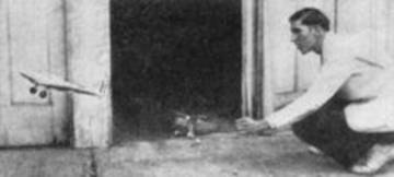
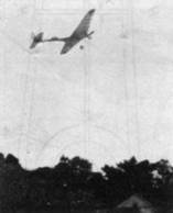
Exhaust stacks should be painted black and glued on the nose of the "Battle." Insignia should either be pasted on or painted with lacquer in the places shown. A radio mast will enhance the appearance of our model as will also identification numbers. The tail wheel is either balsa or hardwood and held in place by an aluminum fork. Paint it black with silver discs. When the model is all assembled, glide it carefully over tall grass and add weight in front if it stalls or bend up the elevators if it dives. When all adjusted, a four strand motor if stretched will take 1200 turns with a winder, of course, and a six strand motor 960 turns. If the model is rather heavy, eight strands may be necessary and this motor will take 825 turns. The finished model should weigh around 1.4 oz. and the average duration runs around 60 seconds. Good luck!
|
Bill of Materials |
|
|
1 |
1/16" x 2 x 24" sheet balsa |
|
1 |
1/32" x 2 x 24" sheet balsa |
|
3 |
1/64 x 2 x 24" sheet balsa |
|
2 |
7/8 x 1-3/4 x 1-7/8" balsa blocks |
|
1 |
3/4 x 1-7/8" square balsa block |
|
2 |
5/8 x 7/8 x 1-1/4" balsa blocks |
|
2 |
sheets tissue |
|
1‑oz. |
cement |
|
1‑oz. |
wood filler |
|
1‑oz. |
clear lacquer |
|
2‑oz. |
banana oil |
|
8‑feet |
brown rubber |
|
1 |
1/16 x 1/4" bamboo |
|
1‑foot |
No. 15 music wire |
|
1‑oz. |
silver paint |
|
3‑cans |
lacquer, red, white and blue |
|
2 |
wheels 1-1/4" diam. |
|
6 |
washers |
|
|
cellophane |
|
|
spaghetti tubing and aluminum tubing |
|
|
sheet aluminum |
Scanned From March 1937
Model Airplane News
![]()
![]()
![]()
![]()
[ Home ] [ Previous Plan Pages ] [ Special
Things ] [ Earl Stahl Plans ]