AT A TIME when gasoline model design is showing
an increasing tendency for complicated structural design, it will be a distinct
relief for model builders with little experience, as well as for the expert, to
find a model which is above the average in looks and performance, yet is simpler
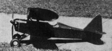
to build than the majority of rubber-powered models now on the market. The "Cavu"
(airway abbreviation for ceiling and visibility unlimited) was originally
designed with that purpose foremost, and the fact was also taken into
consideration that a large number of model builders do not have completely
equipped workshops. Only the simplest tools are required in the construction of
this model; a razor blade, a pair of pliers and other simple tools being all
that are necessary.
Upon completion of the model, any builder will
find that he has a model which he may well be proud of, both as to looks and
performance. The specifications as given are as accurate as could be determined
by actual measurement with a stop-watch. The speed of 24 m.p.h. was reached with
the design propeller turning over at approximately 3200 r.p.m.s., and by minor
adjustments a speed of 27 m.p.h. can be reached. However, the cruising speed of
24 m.p.h. provides an excellent means for climb and radius of turn.
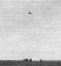
On its first flight, this model took off from a
cinder runway without any aid whatsoever, climbed to a height of 200 feet, flew
across the width of the airport, over the hangars and glided to a perfect
landing in an adjoining pasture. The total length of the flight was seven
minutes, of which two and one-half minutes was engine run. The flight was made
at about 7:00 in the evening; obviously there were no thermals to aid the ship
in its performance.
Since that time, the ship has completed 53
flights with times ranging from two to fifteen minutes, the length of each
flight having been determined beforehand by the amount of gas put in the gas
tank. The most gas that has been used to date was half a tank full, or
approximately 1/8 of an ounce, which gave the model a flight of 15 minutes and
42 seconds.
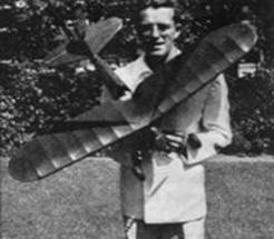
With this performance, and the ease of
construction, which will he apparent by studying the drawings, combined with the
convenient small size and the fact that it can be carried completely set up and
ready to fly in an ordinary car, model builders will find that, for purposes of
demonstration or sport, this model is unequaled. Its simple though rugged
construction makes minor repairs a matter of only an hour or so, and so far as
the author can determine a model that can be seriously damaged only through
striking some object head on, or being stepped on. Irregular landings (which
incidentally are few and far between) caused by gusts of wind so far have no
effect upon the model whatsoever.
In other words, fellows, this model's got
everything, so let's get going, and by putting in a couple of hours a day,
before you know it she will be flying right out of your workshop.
Fuselage
The first step in construction will consist of
enlarging the plans to full size. Study the drawings carefully. After the side
view has been enlarged to full scale, place a sheet of wax paper over the
drawing and pin the longerons in place on the drawing, then cut the struts to
fit at the stations as indicated and glue them in place. Next cut the diagonal
members to fit and glue them in place. Use plenty of glue to insure maximum
strength. After you have finished the one side, lay it aside and allow it to dry
completely while building the other side. Upon completion of the second side,
leave it in place and cut out seven cross braces 2-1/8 inches long. Lay aside
three of them, and, working rapidly, glue four of them upright; one at top of
station 2, one at the top of station 5, one at the bottom of station 5 and one
at the bottom of station 3. Place a drop of glue on the projecting end of these
four cross braces and fit the other side down upon them, aligning the two sides
and propping them with bottles or batteries, or any vertical sided object, and
allow the glue to dry thoroughly. When it is dry, take the other three cross
braces 2-1/8 inches long and glue at the top of stations 3 and 4 and the bottom
of station 4. Allow them to dry thoroughly. Next pinch the two sides together at
the tail and glue thoroughly, allowing the longerons to assume their own curve,
making sure that they are curved equally. Hold the tail together until it dries,
either with pins or with binding. Then cut and glue cross braces to fit at
stations 6 and 7. Next cut a cross brace 1-5/8" inches long and one 1 inch long
for the top and bottom at station 1. The top cross brace will be removed later
and the engine will serve as the cross brace. Cut cross braces to fit at the
bottom of station 2 and one to cross the fuselage where the rear landing gear
wire attaches.
Now cut out the formers and glue formers 2A to
7 inclusive in their respective positions and insert the stringers. Next cover
the cockpit section with the proper two pieces and, after they have dried
thoroughly, cut out the cockpit hole with a sharp razor. Glue the carved pieces
to the sides of station 1, as shown in the cowl detail drawing and then glue the
side stringers in place. Next cut and bend the landing gear wires to shape. Bind
the front wire to the cross brace at station 2 and the rear wire at the cross
brace between stations 2 and 3 as shown in the side view. Then cut the balsa
fairing to fit between the two wires, bind it in place and then spread glue
evenly over the whole landing gear. Now glue the bottom fuselage stringers in
place. Shape the tail skid with spring wire or bamboo, as preferred, and glue in
place with the balsa support. Carve out the headrest, but do not put in place
until the fuselage has been covered later on. Carve the nose block to shape,
split in half vertically, hollow to about 1/16" inch wall thickness, and on each
half make the necessary cutouts for the propeller and engine cylinder as shown
in the front view. Incidentally, the drawing shows the grain as running fore and
aft, but this should be corrected to run up and down as shown in the front view.
Now cut out formers 1 and 2 and glue the cowl
stringers in place as shown in the cowl detail and cover with the 1/32 of an
inch stock; then, as shown in the drawing, cut the top of the nose block off and
glue it to the cowl. Cut the hole in the top of the cowl for access to the gas
tank when in position, and the cowl is complete. Next cut out and place the gas
tank cradle as shown. Then fit the engine mounts, using a beveled joint at
station 1 and the diagonal, glue in place and reinforce with flat stock as shown
in the cowl detail. This engine mount is for use with the Elf engine, but may be
varied slightly to accommodate other engines of similar weight and power. Remove
the cross brace at the top of station 1 and place the motor in position. Shape
the engine mount blocks and drill them at the forward end to fit the particular
motor which is used. Note that in the side view the propeller is shown with a
down thrust from a zero stabilizer angle. This down thrust angle as measured
from a zero stabilizer setting should be approximately 1-1/2 degrees. It may be
accomplished by either placing the engine mounts in at this angle or by
inserting washers between the engine frame and the mounts at the rear mounting
holes.
Now build the battery box with the one side
closed only by the spring wire as shown, which will press the batteries against
the copper sheet at the other side and maintain a good contact. A rubber band
will serve to hold the batteries firmly in place while in flight. Solder the
wire leads to the spark coil and then place the spark coil as shown and bind to
the cross brace at the bottom of station 4. Bind the condenser to the cross
brace at the top of station 2 bringing the leads through the former alongside
the longerons to the timer. Wire the components of the engine in accordance with
the standard wiring diagram as provided by the manufacturer.
Place the lower portion of the nose block in
position and glue the small pieces of aluminum provided midway along station 1.
Drill a small hole in one end which projects over station 1 and with small
screws hold the lower portion of the nose block in place. Glue the spaghetti
tubing to the edge of the cockpit, cut out and attach the windshield and the
fuselage is ready for covering.
Wing
Although it is not absolutely necessary that
the plan view of the wing be enlarged to full scale, unless the builder has
already had considerable experience in building wings, it is suggested that the
plan be enlarged and the wing be constructed right on the plan. Complete the
plan of the left panel to correspond to the right panel and build each panel
separately, leaving sufficient length on the spar and leading edge at the center
section to overlap and be securely joined later on. Cut out the ribs as shown in
the full scale drawing, notching each rib to receive the leading edge and main
spar and trimming the trailing end to fit the trailing edge as shown. Cut the
spar material to the proper length and mark the rib positions on the spar, then
slip the ribs on the spar, aligning them carefully, and glue in place securely.
While this is drying, round off and shape one corner of the 5/16 inch square
leading edge material, and, as soon as the ribs have dried thoroughly to the
spar, glue the leading edge in position.
Next shape the trailing edge material to the
proper form and glue in place. While this is drying, carve the tip outline from
the 1/4 inch flat stock to conform to the drawing, glue in place and reinforce
the forward piece with the diagonal brace as indicated. To join the two panels,
cut the overlapping ends of the main spar and leading edge at an angle so that
when fitted together the wing will show 3 inches dihedral at each tip. Lay one
panel flat on your table and glue the center section of the main spar and
leading edges together propping the wing tip of the other panel 6 inches up from
the flat surface of the table. Allow this to dry, then bind the center section
of the spar and leading edge with the silk thread and again coat with glue. Then
carve the trailing edge cutouts and glue them in the proper position. To
complete the construction, the wing strut reinforcements are glued securely in
place and the entire unit is sanded with fine sandpaper.
From the three view drawing, project the wing
struts to their true length, carve each to a streamlined shape and trim the
lower ends to fit flat against the side of the top longeron and the upper ends
to fit flat against the strut bracings in the wing structure. Glue the struts in
place on the fuselage, lay the completed wing on the struts and complete the
final trimming of the struts to give the wing a one degree angle of incidence
with respect to a zero stabilizer setting. Do not glue the wing in place until
after both wing and fuselage have been covered.
Tail Surface
The construction of the tail surface is
extremely simple; merely enlarge the drawing to full scale and glue the
respective elements in position as shown. Construct the rudder and vertical fin
as one complete unit, the horizontal stabilizer as one complete unit, and each
elevator separately. The elevators are joined to the stabilizer by the simple
aluminum hinge as shown in the full scale drawing, which is merely forced into
the balsa and glued in place.
While the tail surface units are drying, mark
the propeller block as shown and carve your propeller. Different propellers can
be used with different engines. This particular design will give a 6 inch pitch
propeller and the Elf engine turns it over at approximately 3200 r.p.m.
Covering and Assembling
The model is covered with ordinary Japanese
tissue throughout, which, after being put on the framework, is sprayed with
water. allowed to dry and then given three coats of pigmented dope. The color
and trimming is, of course, to individual taste. The original model was colored
a brilliant international orange, trimmed with black. For a high gloss finish,
give the covering a final thin coat of lacquer. To assemble the model, glue the
lower end of the rudder spar to station 8. Minor adjustments in rudder setting
may be accomplished by inserting a pin in the leading edge through the
stabilizer leading edge. Now when all the units are in place, including two
battery cells in the battery box, check the balance of the fuselage by
suspending from the diagonal wing strut. The fuselage should balance in flying
attitude very close to station 3. Cut away the covering on the wing from the
wing strut braces and glue the wing in place and the model is ready for the test
flight.
Testing and Flying
The ship is easy to test because of its very
convenient size and preliminary tests can even be run in the back yard. They
consist of a series of successful pushes on the tail; each of increasing force
until the model leaves the ground and glides for a short distance. Note
carefully whether the model has a tendency to climb too steeply and then squash
to the ground, or whether with even a moderately hard push it merely runs along
the ground with the tail high. The ship should, with a push, approximately 18
m.p.h., leave the ground about 3 feet from your hand and climb from the momentum
to about 4 feet, nose down smoothly and surely and glide in to hit squarely on
both wheels. For heaven's sake, be sure when you make this test that there isn't
a fence 50 feet in front or else there will be some minor repairs. With these
glide tests to start, we next proceed to the primary power tests.
Tie a string around the center section of the
wing and have about 10 feet trailing; start the engine, and when it is running
smoothly retard the spark until the engine is not delivering quite full power.
Get behind the model, holding on to the string, and then run with it and allow
the model to take off under its own power. Watch carefully for any tendency to
stall or go into a steep bank in either direction. The take off should be steady
and in a straight line. Make any necessary adjustments to the rudder and
elevators until this is accomplished, then remove the string, put in a couple of
drops of gas, offer a prayer to the model builders' god and let it go.
With reasonable care in construction and
primary testing, it should climb to about 100 feet and fly for about three
minutes and show a good, steady, but not too flat, glide when the engine cuts.
After your first complete free flight has been accomplished and possibly some
minor adjustments made, you will find that the performance is extremely
consistent and will vary only at your own desire through changing the control
surfaces.
|
Bill
of Materials |
|
|
|
Fuselage |
|
Longerons, 4 pieces 3/16" sq. x 26" long. |
|
Struts, cross braces and diagonals, 3
pieces 3/16" sq., 24" long. |
|
Stringers, 8 pieces, 1/8" sq., 24" long. |
|
Former material, 1 piece, 1/16" x 2" x
24". |
|
Cockpit cover, 2 pieces, 1/32" x 2" x 4". |
|
Engine cowl stringers, 1 piece, 1/8" sq.
x 12". |
|
Nose block, 1" x 2" x 4". |
|
Headrest, 1 piece, 3/4" x 5/8" x 4-1/2". |
|
Windshield, stiff celluloid, 2" x 4" cut
to desired shape. |
|
Engine mounts for Elf engine, 1/4" x 3/8"
x 1-1/2", pieces hard wood. |
|
Engine mount supports, scrap balsa, 1/8". |
|
Gas tank cradle formed from one piece
1/2" x 3/8" x 1-7/8". |
|
Battery box, 1/8" flat stock. |
|
|
|
Wing |
|
Wing ribs cut from 3 pieces, 1/16" x 2" x
24" flat stock. |
|
Main spar, two pieces, 3/16" x 3/4" x
24". |
|
Leading edge, 2 pieces, 5/16" sq., 24"
long. |
|
Trailing edge, 2 pieces, 1/2" x 1/4" x
16". |
|
Center section trailing edge carved from
3/16" flat stock. |
|
Wing tips carved from 1/4" flat stock. |
|
Strut braces 3/8" x 1/2" x 3/4". |
|
Wing struts, 1 piece, 1/2" x 1/4" x 18". |
|
Wing tip braces, 1 piece, 1/8" x 1/4" x
6". |
|
|
|
Tail
Surface |
|
Stabilizer: |
|
Main spar 1/8" x 1/4" x 15". |
|
Leading edge, 2 pieces, 3/16" sq. x 7". |
|
Ribs cut from 1 piece, 1/16" x 1/4" x
15". |
|
Tips carved from 3/16" flat stock. |
|
Elevators: |
|
Main spar, 2 pieces, 1/8" x 1/4" x
7-1/2". |
|
Trailing edge, 2 pieces, 1/8" x 1/4" x
6". |
|
Ribs cut from 2 pieces 1/16" x 1/4" x
12". |
|
Tips carved from 3/16" flat stock. |
|
Inner trailing edge, 2 pieces 1/8" x 1/4"
x 3". |
|
Hinges cut from soft aluminum. |
|
Rudder: |
|
Main spar 1/8" x 1/4" x 7-1/2". |
|
Leading edge, 1/4" sq. x 6". |
|
Trailing edge, 1 piece, 1/8" x 3/8" x 7". |
|
Tip and bottom former carved from 3/16"
flat stock. |
|
Ribs cut from 1 piece 1/16" x 1/4" x 15". |
|
Base rib 1/4" sq. x 4". |
|
|
|
Landing Gear |
|
Landing gear funned from 1/16" spring
wire 26" long faired with 3/16" soft balsa. |
|
3-1/4" air wheels. |
|
Tail skid formed from 1/32" spring wire
or bamboo with 1/8" flat stock balsa support. |
|
|
|
Propeller Block |
|
Propeller block 1-1/4" x 1/2" x 11 ". |
|
Spinner carved from piece 1" x 1" x 5/8". |
|
|
|
Miscellaneous |
|
Silk thread for binding landing gear,
spark coil and condenser to cross braces. |
|
2 pieces thin aluminum 1/2" x 1/4" for
nose block attachments. |
|
Spaghetti tubing for cockpit edge. |
Entire ship covered with Japanese tissue with
three coats of dope, colored to suit, then finished with one thin coat of
lacquer. In every case in the above list of materials, sufficient leeway has
been allowed for unexpected breakage, and the builder will find that he has more
than enough material if he uses reasonable care in construction.