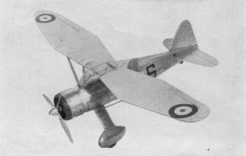
A glance at the front‑cover drawing will show that this model to as
exact replica or the full‑size Westland monoplane.
The Plan Page
[ Home ] [ Previous Plan Pages ]
[ Special Things ] [ Earl Stahl Plans ]
gt-hunter1@home.com
Building the Westland "Co‑Op"
by PAUL W. LINDBERG
Model Editor
and Model Designer for POPULAR AVIATION.
A
glance at the front‑cover drawing will show that this model to as
exact replica or the full‑size Westland monoplane.
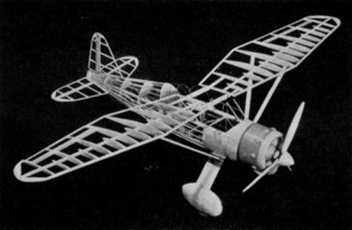
The Westland monoplane model before covering, showing the
peculiar wing outline.
THIS machine is intended for use in the Royal Air Force and is capable of very high speeds. Its clean lines, together with good stability, assures us of excellent performances. All improved features have been worked into the model, such as movable controls with aluminum hinges, together with all other details to make it an exact scale model.
COLOR SCHEME
Entire model -‑ aluminum, front part of cowl -‑ red, details -‑ black.
CONSTRUCTION OF FUSELAGE
It is necessary to place a sheet of ordinary wax paper over the plan to prevent cement from sticking to it. In building the fuselage, construct one side at a time. The longerons, vertical and diagonal braces, etc., are held in place until securely cemented, by inserting straight pins on either side of strips.
After the two fuselage sides are completed, they are pinned to top view of the plan in such a manner that the top longerons face down and the sides are at right angles with the table. The cross-members are now cemented in place, forming a rectangular fuselage.
Cut formers from 1/16 - inch sheet balsa and cement in their respective positions as shown on plan.
Balsa nose plate is built up from 1/8 - inch sheet balsa. Stiff paper is required between nose plate and formers.
All framework which consists of the fuselage cabin is made of wire.
CONSTRUCTION OF MOTOR
The cylinders are carved and sanded from balsa blocks. When nine cylinders have been formed, wind heavy thread around them to represent fins. Make crankcase from two pieces of balsa. Rocker arms housings, push rods and other small details of motor are made of balsa.
CONSTRUCTION OF WINGS
Cut all ribs from 1/16 - inch balsa. Pin the spar in position on the plan. Now, cement ribs in their proper locations. The leading and trailing edges are cut and sanded to shape and cemented to the ribs.
The panels carry movable ailerons which are a great help in controlling the flights. Make wing tips from 1/16 - inch thick balsa. We highly approve of this type of wing tip, because it is much easier to construct and neater in appearance.
CONSTRUCTION OF ELEVATOR AND RUDDER
These are built from 1/16 - inch square and flat balsa, and are constructed on the plan. Their construction is very simple, therefore, no difficulty should be encountered here.
CONSTRUCTION OF THE LANDING GEAR
After the struts have been cemented together, cement them to the streamline wheel coverings. The wheel coverings are carved from three pieces of balsa which have been cemented together. The method in which the landing gear struts are attached to the fuselage is plainly shown in detail on plan.
COVERING THE MODEL
Apply tissue to the various framework members, using a light grade model airplane dope to fasten it to the outer edges. Stretch tissue as tightly as possible to remove all wrinkles. When edges have dried, apply coat of water to tissue. When all water has dried completely, tissue will become taut. May we suggest that you pin wings, elevator and such to flat surface. This prevents warping.
ASSEMBLY
After the various parts have been covered, wing panel can be cemented into position. The wing struts are next cemented into position. Markings on both sides of fuselage can be painted on white paper, cut out and cemented to model. Other small details can be drawn with pen and ink and cemented to correct positions on model. All details clearly shown on plan.
Scanned from Popular Aviation
Date Unknown
![]()
![]()
![]()
![]()
[ Home ] [ Previous Plan Pages ] [ Special
Things ] [ Earl Stahl Plans ]