|
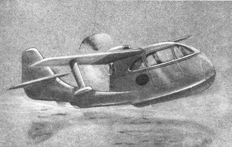
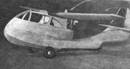
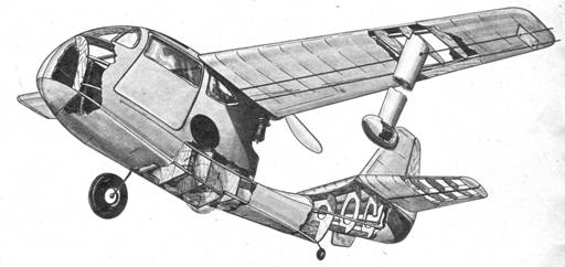
‘SEABEE’ by MARSHALL S. GREEN
FOR the many control line fans who
get a real kick out of realism, no greater thrill can be experienced than
piloting this miniature of Republic's smart, new, personal amphibian. This
particular scale model has been designed to take off and land on water, which
in itself constitutes a major incentive to build it. Since drawing up the first set of plans many
revisions and structural simplifications suggested themselves; these have
all been included here and it is thought that anyone with a little model building
experience will have no difficulty in following the drawings and the text. LAYOUT—Having fastened a
40" x 60" piece of clean, uncreased brown
wrapping paper onto the dining room table with scotch tape, start by laying
down the centerline for the plan view and the base line for the elevation and
then completing the two grids of 1/2" squares required for each view;
be exact and keep the lines parallel, for upon accuracy depends the fit of
all formers and bulkheads and the ease with which the hull can be finally
sheeted. With the aid of given dimensions and the grid,
draw up the elevation (side view) and plan, flow in the curves smoothly with
"french curves" and "sweeps,"
if available; if not do the best possible by freehand for small curves and,
for the long sweeps, a straight grained piece of 1/8" x 3/16" hard
balsa strip in place of a regular "spline."
The balsa spline works every bit as well as a
Copenhagen ship sweep and has the extra advantage of being adaptable to any
desired contour. Despite the fact that neither side view nor elevation is
used in actual construction of the hull, they are imperative for checking the
accuracy of bulkheads and as a guide to the shape of nose block, formers,
engine nacelle, as well as for building the empennage.
HULL—Lay
out bulkheads as shown, transfer all but Stations 1 and 6 onto medium
1/8" sheet. Bulkheads No. 1 and No. 6 are cut out of 1/8" 3-ply.
Check each station with the drawing and make sure that notches for strake,
chine and stringers are accurately located. Bulkhead No. 4a has cemented to
it a block made from a piece of 1/2" thick oak, maple or similar
hardwood in which two holes are drilled as shown. The landing detail gear on
sheet No. 2 should explain the function of the block. Actual assembly can now start. Unlike the majority
of models which are built over the plans in the initial stages, the contours
of the Seabee made this impractical
and the construction method known as "building in air" was resorted
to. This means that excepting for the keel and flying surfaces which can be
assembled directly on top of the drawing, all structural components starting
with the bulkheads are added and cemented in place while the structure is
held free from the construction board. Check perpendicular inclination of bulkheads
against the layout and sight along keel, fore and aft, to see that they are
in perfect alignment behind each other. Lay in 3/16" square chines
and sheer beams, formers, wing platform, etc. to complete the basic
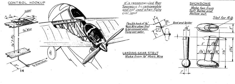
structure. Then, with the sketch on sheet No. 2 as a guide, make up the
control mechanism and install it in the hull. Make sure that tie-rod to the
elevator does not bind on any of the bulkheads it passes through. Cut out
sea-rudder from thin alum. and attach it to the
keel. EMPENNAGE — Before sheeting the
hull it is recommended that the stab and elevator be made and assembled complete
with hinges and control horn. The only uncoventional
feature of the empennage is the inverted stab which is sanded to an
approximate Clark-Y type of profile after assembly. Cloth elevator hinges are
quite satisfactory. Cement stab, elevator, fin and rudder as a unit to the
boom, then couple up tie-rod and elevator horn so that movement is smooth,
free and without excessive play. SHEETING—Were it not for the fact
that an extremely flexible piece of 1/16" sheet were used on the
original, some difficulty might have been encountered in sheeting the boom
above the strake between stations 9 and 11. However, if flexible sheet is
not at hand, this section can certainly be planked without any trouble. The
rest of the hull takes sheets in 2" widths of soft 3/32" balsa
without the remotest chance of splitting or causing any grief. Do not sheet
above former A, between stations 1 and 4; instead use strips of 1/16 sheet to
form window outlines—window aft of station 4 is fretted out of the sheet
covering. WING—Lay out the wing and cut
out required ribs from medium 3/32" balsa. Form trailing edge and
assemble each half-wing separately; when dry, fasten together with
appropriately shaped 1/16", 3-ply gussets so that each tip is raised
1-1/2" above horizontal. Apply soft 1/16" sheet to leading edge
and, if desired, 1/16" and 3/16" cap strips over each rib. From the plans, shape up the soft balsa block
which contains the window above the wing platform between stations 2-a and 4, hollow it out to save weight and cut out the
window opening. Attach this block to the l.e. as
indicated. Check contours of engine nacelle against motor to
be used before carving and hollowing. The nacelle is then also permanently
attached to the center section. In the original model the wing was cemented to
the hull, there being no transportation problems to contend with. However
the center section is so designed that the wing can be made removable if
deemed advisable. Sponsons are carved according to
the drawings and are made removable for overland flying. Reinforce ribs at sponson junction point—this was not done on the original
but the particular rib in question was made out of 1/8" 3-ply and
considered to be stout enough to stand up under imperfect landings. FINISHING — Complete the ship by
carving out the nose block to specifications and set about the task of
sanding down the 3/32" sheet "skin" with progressively finer grades
garnet paper until it is about 1/16" thick and satin smooth. Apply two
coats of filler, sanding after each coat, then follow with two coats of
lacquer or dope. Sand lightly with 4/0 wet-or-dry and then cover with a good
grade of tissue. Dope at least 4 extra layers of Silkspan
onto the bottom to insure water resistance and again use the wet-or-dry.
Finally, apply 6 coats of pigmented dope or two coats of good grade enamel
and set aside to dry. FLYING—Connect up control lines
and move ignition components about until the c.g.
falls in the location shown. Inspect the surfaces for correct trim and the Seabee is ready for its first test
flight. At the time of writing the ship has not yet been
tried on water, local ponds being ice bound, so no hints can be given of its
behavior under these conditions. From the test flights over snow which have
so far been made, the indications are that flying over water next Spring is
going to be successful. Test flying should be done with caution until best
c.g. location has been determined and the
controlling influence of the elevator properly assessed. With a motor of .29
displacement the ship flies extremely well and safely, is easy to handle and
rather slow (perhaps 25 mph), but it requires rather a long takeoff run and
for this reason it is suspected that such a small motor would not take it off
water. It was after a motor of .60 displacement
was fitted that trouble developed which needed drastic corrective measures.
The increased speed promoted a noseover tendency
which full up elevator would not overcome. Happily the ship was flying quite
low and no damage resulted. A new stab was built with an inverted section
and the trouble was entirely eradicated making it certain that no difficulty
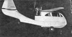
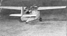
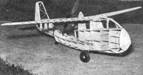
will arise when the ship is eventually tried in its proper element. It should be mentioned that the model appearing in
the photographs has been regarded throughout the trials as a guinea pig and
no attempt was made to "dress it up." Final tests having now been
successfully concluded, the model will be finished properly. To those readers who are diehard "free flighters" it is believed that the Seabee offers something new in Class B
models. The original ship weighed 39 ozs. ready to fly, but the structure has been greatly lightened
in the plans and it should be possible to build to 36 ozs.
which will give a wing loading of about 12 ozs. per square foot. It is further suggested that the boom be
lengthened some 2" and the horizontal tail area increased by 50% to give
better longitudinal stability. Also, the wing profile should be more in
keeping with desirable free flight behavior and could better employ an
airfoil similar in characteristics to the N.A.C.A. 4412, Gottingen Sections
398 or 398R or similar high lift section. It should be borne in mind that in
all pushers c.g. location is of paramount
importance and upon its ideal location will largely depend
the stability of the ship. Much time and effort must be patiently expended
until correct balancing point is arrived at; only then may the ship be
allowed its head under full power. Scanned From January 1946 Model Airplane News |
![]()